Remote controller with weekly timer
Owner’s Manual
– 5 –
EN
2
PARTS AND THEIR FUNCTIONS
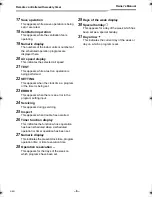
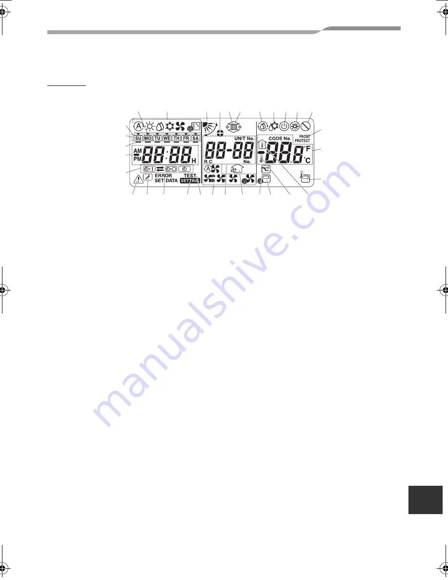
LCD area
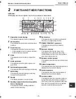
All displays are shown lighted only for the purposes of description.
1
Operation mode display
The selected operation mode is displayed.
2
Air direction
This indicates the air direction which has been
selected.
3
Fixed louvers
This appears when the louvers are fixed.
* It also appears when the remote controller
function has been selected.
4
Filter
This appears when it is time to inspect the
filter.
5
Grille up/down
This appears when the grille is goes up or
goes down.
6
Self-cleaning operation
This appears while self-cleaning is underway.
7
Defrosting
This appears while defrosting is underway
during a heating operation.
8
Ready
This display appears on some models.
9
Heating ready (indoor fan stops while
this is displayed)
This appears before a heating operation
starts or while defrosting.
10
No function
This appears when a button is pushed but
there is no corresponding function.
11
FROST PROTECT operation
This appears during a frost protection
operation.
12
Numeric display
This displays the numeric value of the
temperature, the numerical order of the
trouble history events or the code numbers
when the functions are set.
13
Remote control sensor
This appears when the remote control sensor
is used.
14
Indoor temperature
This appears when the intake temperature is
displayed on the numeric display.
15
Set temperature
This appears when the set temperature is
displayed on the numeric display.
16
Central control
This appears when key operation limits are
being enforced by the central controller or
other unit or when key operation limits have
been set in the program for the scheduled
operation currently being executed.
1
31
2 3 4 5
6
7 8 9 10
22
23
24
25
26
27
28
29
30
21 20 19
18 17 16
15
14
11
12
13
4-EN
+00EH99677901_01EN_OM_Remo_Weekly_UL.book Page 5 Thursday, October 8, 2009 2:03 PM
Summary of Contents for Carrier RBC-AMS41UL
Page 26: ...EH99677901 ...


