background image

Wireless remote controller kit

Installation Manual

– 13 –

12

EXPLANATION TO CUSTOMERS

• Hand over the “Owner’s Manual” and “Installation Manuals” to the customer after 

installation works.

• Explain usage and maintenance of the remote controller according to “Owner’s Manual”.

13

HOW TO HANDLE THE REMOTE 

CONTROLLER

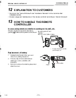
In case using remote controller mounting to the wall, etc.

Check a signal is received correctly by 
pushing 

 button at the position to be fixed.

Replacement of battery

1. Holding the both ends of the cover and 

remove it by sliding downward.

2. Correctly insert 2 AAA alkali batteries 

matching (+) and (-) polarities with 
indications.

3. Push ACL button with something tipped and 

attach the cover.

Put on.

Push.

Mounting screw Truss 
tapping 
Ø0.16” x 0.63” (M4 x 16mm)

• To take off remote controller, 

pull it toward you.

ACL button

Cover

13-EN

+00EH99677601_01EN_remo_IM.book  Page 13  Thursday, October 8, 2009  4:12 PM

Summary of Contents for Carrier TCB-AX21UL

Page 1: ...glish Manuel du proprietaire Télécommande pour climatiseur Type split 15 Français Remote Controller Model name Wireless remote controller kit TCB AX21UL Generic model name Wireless remote controller and Signal receiving unit TCB AX21UL WX TA01UES Wireless remote controller model name Wireless remote controller WX TA01UES Signal receiving unit ...

Page 2: ... SWITCH 11 10 SELF DIAGNOSIS TABLE AND MEASURES 12 11 CAUTIONS FOR INSTALLATION OF THE REMOTE CONTROLLER 12 12 EXPLANATION TO CUSTOMERS 13 13 HOW TO HANDLE THE REMOTE CONTROLLER 13 14 TEST RUN 14 Thank you very much for purchasing TOSHIBA Carrier Remote Controller for Air Conditioner Please read the owner s manual carefully before using your Remote Controller for Air Conditioner Be sure to obtain ...

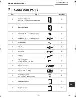
Page 3: ...cable 1 2 Mounting bracket 1 3 Screws 0 16 x 1 0 M4 x 25 mm 2 4 Screws 0 16 x 1 6 M4 x 40 mm 2 5 Wood screws 2 6 Spacer 4 7 Wire joints 2 8 Cable tie 1 9 Pattern template 3 7 x 2 95 mm x 51 mm 1 10 Remote controller 1 11 Remote cotroller holder 1 12 Truss tapping screw 0 16 x 0 63 M4 x 16 mm 2 13 Installation manual 1 14 Owner s manual 1 2 EN ...

Page 4: ...controller Refer to page 11 Allx NORMAL selector switch Set this switch to the NORMAL position for the normal operation of the air conditioner When this switch is set to the Allx position the indoor unit of the air conditioner is turned off RCU SUB RCU MAIN selector switch Set this switch to the RCU MAIN position for normal operation Refer to page 9 for setting to the RCU SUB position PCB CHK swit...

Page 5: ...ch as elevators automatic doors and industrial sewing machines If the Signal receiving unit is installed near a rapid start type or inverter type fluorescent lamp a lamp which does not include a glow lamp it may not be possible to receive the wireless remote controller signal in some cases In order to prevent interference from fluorescent lamps leave a minimum of 6 7 2 m between the Signal receivi...

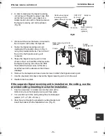
Page 6: ...and use the provided spacers If the Signal receiving unit does not fit in the wall cut spacers to adjust the clearance 3 Connect the Signal receiving unit wiring 2 core cable with the cables extended from the indoor unit Refer to the section on Signal receiving unit wiring Be sure to determine the correct terminal numbers on the indoor unit when wiring the Signal receiving unit The remote controll...

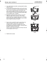
Page 7: ... of the cable tie so that it faces sideways 6 Remove the nameplate and use 2 wood screws to attach the Signal receiving unit 7 Use the provided cord clips to fasten the Signal receiving unit cord to the wall 8 Reattach the face plate If the separate Signal receiving unit is installed on the ceiling use the provided ceiling mounting bracket for installation 1 Insert a screwdriver or similar tool in...

Page 8: ... 6 Adjust the provided spacers so that they are several millimeters larger than the thickness of the ceiling material Pass the 2 supplied screws 0 16 x 1 6 M4 x 40 mm through the spacers and tighten them enough to hold the Signal receiving unit in place 7 Return parts A and B through the gap between the ceiling and Signal receiving unit so that they are contained in the openings Then tighten the s...

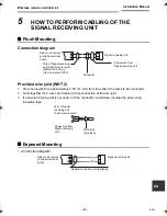
Page 9: ...pecial crimping tool is not used or if the connection is soldered insulate the wires using insulation tape Exposed Mounting Connection diagram Signal receiving unit Power wire from Signal receiving unit Connector Wire of Signal receiving unit Field procurement AWG20 0 5 mm2 UL wires rated 300 V Indoor unit remote controller terminal board Wire of Signal receiving unit Field procurement Wire joint ...

Page 10: ...eously the wireless remote controller with the wired remote controller set one of them as the sub remote controller When setting the wired remote controller as the sub exchange the address connector at the rear of P C board of wired remote controller from master to sub remote controller When setting the wireless remote controller as the sub turn the switch of wireless remote controller Signal rece...

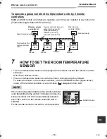
Page 11: ... push the SENSOR button figure below inside of the remote controller cover and check disappears from LCD NOTE If the room temperature data from the remote controller is not transmitted to the unit for 10 minutes or more the sensor at indoor unit side is automatically selected even if the sensor at the remote controller side is selected Fix the remote controller toward the unit as possible Wireless...

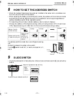
Page 12: ...receiving unit by removing screws of P C board cover of the Signal receiving unit After then fix the cover with screws using a clamp The address switch is inside the cover of Signal receiving unit Contact the dealer for setting of the switch Turn the switch to left for 1 2 and 3 and right for 4 5 and 6 9 SLIDE SWITCH Check the slide switch in the battery box of the remote controller is set to S A ...

Page 13: ...ng attention to the following items Place not exposed directly to cold or hot wind Place not exposed directly to the sunlight Other places where the remote controller is not influenced Goes off Blink 0 5 sec interval Lamp indication Cause Measures No indication even if the remote controller is operated Power supply is not turned on Miscabling between Signal receiving unit and indoor unit Check cab...

Page 14: ...e using remote controller mounting to the wall etc Check a signal is received correctly by pushing button at the position to be fixed Replacement of battery 1 Holding the both ends of the cover and remove it by sliding downward 2 Correctly insert 2 AAA alkali batteries matching and polarities with indications 3 Push ACL button with something tipped and attach the cover Put on Push Mounting screw T...

Page 15: ...n 2 Push the button on the wireless remote controller to start the operation of the air conditioner The and lamps each light under test running The temperature cannot be set by the wireless remote controller with the TEST RUN switch is set to the TEST RUN position 3 Operate the air conditioner in the heating cooling or fan only mode during test running The outdoor unit will not operate for approxi...

Page 16: ... EH99677601 85464369216000 ...

Reviews: