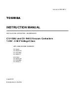
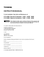
background image

Document: 

VF010H10

TOSHIBA

INSTRUCTION MANUAL

INSTALLATION - OPERATION - MAINTENANCE

CV-1GAU and CV-1HAU Vacuum Contactors
1.5kV - 2.5kV Voltage Class

APPLICABLE MODEL NUMBERS

CV-1GAU
CV-1GAU-P2
CV-1GAUMIL
CV-1GAU-C

CV-1HAU
CV-1HAU-P2
CV-1HAUMIL
CV-1HAU-C

Issued:9/01

Manufactured in the USA

Summary of Contents for CV-1GAU

Page 1: ...UAL INSTALLATION OPERATION MAINTENANCE CV 1GAU and CV 1HAU Vacuum Contactors 1 5kV 2 5kV Voltage Class APPLICABLE MODEL NUMBERS CV 1GAU CV 1GAU P2 CV 1GAUMIL CV 1GAU C CV 1HAU CV 1HAU P2 CV 1HAUMIL CV 1HAU C Issued 9 01 Manufactured in the USA ...

Page 2: ...contact Toshiba address all correspondence to Field Service Department Toshiba International Corporation 13131 West Little York Road Houston Texas 77041 USA or call 713 466 0277 800 231 1412 800 527 1204 Canada Fax 713 466 8773 Please complete the following information for your records and retain with this manual Model ___________________________________ Serial Number _____________________________...

Page 3: ...ty damage if you do not follow instructions Means that you might be seriously injured or killed if you do not follow instructions Severe property damage might also occur Means that you might be injured if you do not follow instructions Equipment damage might also occur NOTE Gives you helpful information READ SAFETY SIGNS To avoid injury you must read and follow all safety signs Keep the safety sig...

Page 4: ...nce with established safety practices 4 Be trained and authorized to perform the service maintenance or repair of this equipment 5 Be trained in the proper care and use of protective equipment such as rubber gloves hard hat safety glasses face shield flash clothing etc in accordance with established practices 6 Be trained in rendering first aid SAFETY CODES Toshiba CV 1GAU and CV 1HAU vacuum conta...

Page 5: ... injury death fire explosion and property damage Turn off and lock out Primary and Control Circuit Power before servicing Keep all panels and covers securely in place Never Defeat Modify or Bypass any Safety Interlocks Qualified Operators only DANGER ...

Page 6: ...Mounting the Contactor 11 Main Circuit Cable Connections 11 Control Circuit Connections 11 Control Terminals Location 11 PRE ENERGIZATION CHECK 12 General 12 Electrical Checks 12 OPERATION 13 Moving Contactor from Disconnected to Connected Position 13 Moving Contactor from Connected to Disconnected Position 13 Configuration of the Drive Unit 14 MAINTENANCE 15 Maintenance Program 15 Maintenance Rec...

Page 7: ...for Vacuum Check 21 Electrical Service Life 22 Mechanical Service Life 22 Interrupter Wipe Measurement 22 Auxiliary Overtravel Measurement 22 Lubrication 22 STORAGE AND DISPOSAL 23 Storage 23 Inspection during Storage 23 Disposal SPECIFICATIONS 24 Table 4 Ratings 24 WARRANTY AND LIMITATION OF LIABILITY 26 ...

Page 8: ...ce and longevity Dimensions shown in the manual are in English and or their metric equivalent This manual is divided into major sections of interest as follows GENERAL DESCRIPTION Provides a description of the equipment information on major components and how they function plus rating information RECEIVING INSPECTION AND HANDLING Describes procedures for receiving unpacking inspecting and handling...

Page 9: ... HAU P2 GAUMIL HAUMIL GAU C and HAU C P2 models have a fast opening time MIL models are for mechanical interlocking C models have a 480 550Vcontrol voltage Figure 1 Front of Contactor The information presented in this manual is common to all models unless otherwise noted Refer to the Ratings Tables in the SPECIFICATION section of this manual for model details Contactor Components 1 Power Terminals...

Page 10: ...or is provided On Off Indicator Indicates if the contactor is OFF Green or ON Red When the indicator reads OFF the main contacts of the contactor are open When the indication is ON the main contacts are closed See Figure 3 Figure 3 ON OFF Indicator Figure 4 Outline Drawing ...

Page 11: ...iciently to check for missing parts or concealed damage 3 Check for the presence of accessories that are shipped with the contactor Contactor wear gauge Figure 5 4 Keep the contactor upright Never lay the contactor on its side or upside down This may cause damage File a claim with the carrier for any damaged or missing items and immediately notify the nearest Toshiba representative Do not install ...

Page 12: ...t the installation location a space heater should be installed inside the contactor enclosure NOTE Temperature altitude capacitor switching or other conditions outside of the usual limits may require derating or other special equipment Contact your nearest Toshiba representative for additional information RATING VERIFICATION Prior to installation the maximum current rating and typeform of the cont...

Page 13: ...35 mm Class 8 8 M8 or M10 hex head bolts 2 flat washers a lock washer and a nut While securely preventing the nut from rotating with a wrench torque the bolt to 250 315 kgf cm 18 23 ft lb for M10 bolts or 450 565 kgf cm 32 41 ft lb for M12 bolts Use two wrenches to torque the connection to prevent applying excessive force to the terminal which can damage the frame CONTROL CIRCUIT CONNECTIONS Hazar...

Page 14: ...pment must be removed Install all panels guards and covers if removed Check for any loose connections and confirm that all wiring is correct per wiring diagrams A supply of spare parts should be established Instruction manuals and diagrams should be collected and filed ELECTRICAL CHECKS Electrical shock hazard Do not touch energized components during a test using auxiliary power An electrical insu...

Page 15: ...osition 2 Verify that the position indicator reads ON Red Figure 9 MOVING THE CONTACTOR FROM THE ON TO THE OFF POSITION TO MOVE THE CONTACTOR TO THE OFF POSITION 1 Turn OFF circuit control power to move the contactor to the OFF position 2 Verify that the position indicator reads OFF Green Figure 10 Figure 9 Closed contactor ON indication Figure 10 Open contactor OFF indication ...

Page 16: ...f the Drive Unit SWITCHING OSCILLATION POWER TIMER VOLTAGE DETECTION CC A1 A2 52 A1 A2 AC DC CONTROL SOURCE 100 240V AC DC COMMON CV 1GAU C CV 1HAU C 460 550 VAC NO NC NO NC AUX AUX R U V S W T AUX NO NC NC NO AUX OPTIONAL AUX AUXILIARY CONTACTS ...

Page 17: ...s to contaminate insulating materials Contaminated insulators can allow a short circuit or ground fault to occur NOTE Refer to the SAFETY section of this manual for important information MAINTENANCE RECORD Keep a permanent record of all maintenance work At a minimum this record should include information on 1 Items inspected 2 Reports of any testing 3 Equipment condition 4 Corrective actions or ad...

Page 18: ...on Frequency Once every 6 months 3 Periodic Inspection Inspection is performed with the contactor de energized The lubrication of sliding and rotating parts is checked and the mechanism is lubricated if needed Inspection Frequency Once every year or every 50 000 operations at 1 5kV or every 10 000 operations at 2 5kV NOTE Refer to Table 2 for the schedule of Periodic Inspections 4 Unscheduled Insp...

Page 19: ...Lubricate if necessary Main Circuit Terminals and movable conductors Visual inspection Tighten using screwdriver or wrench Make sure there is no discoloration or loose fasteners Check the cause and repair Tighten connections to contactor See Table 1 for tightening torque specifications Loose bolts nuts or screws Tighten using a wrench Make sure all bolts nuts and screws are tight See Table 1 for t...

Page 20: ...orque specifications Drive unit Visual inspection Check for overheating and discoloration Contact factory Wiring Visual inspection Tighten using a screwdriver Check for discoloration and tightness Repair if disconnected Tighten if loose See Table 1 for tightening torque specifications Insulation Resistance Measure ment Resistance from main circuit to ground Measure insulation resistance between ph...

Page 21: ...necessary replace faulty parts Table 3 Wear and Replacement Check Values Dimensions are MM inches Typeform CV 1GAU CV 1HAU CV 1GAU P2 CV 1HAU P2 CV 1GAUMIL CV 1HAUMIL CV 1GAU C CV 1HAU C Vacuum Interrupter Wipe New Needs Replacement 1 5mm 059 0 5mm 019 1 5mm 059 0 5mm 019 2 5mm 098 0 5mm 019 1 5mm 059 0 5mm 019 Aux Contact Overtravel New Needs Replacement 2 9 3 2mm 114 125 0 5mm 019 2 9 3 2mm 114 ...

Page 22: ...g this test with recommended voltage and normal contact spacing is extremely low and well below the maximum permitted by standards As an additional safety measure however it is recommended that all personnel keep at least 1 meter 3 3 ft away from the vacuum circuit breaker while this test is performed Radiation exposure hazard X rays may cause illness or injury Stay at least 1 meter 3 3 ft away fr...

Page 23: ...illiamperes the interrupter has a sufficient vacuum level After the test is complete discharge any residual static charge from the primary terminals of the circuit breaker If a vacuum checker or AC hi pot tester is not available a DC hi potential test may be conducted If a DC test is conducted the test voltage must be increased to 14kV DC The test duration for DC tests and the criteria for accepta...

Page 24: ...rted then the end of the service life has been reached The maximum number of open close operations is 500 000 regardless of the magnitudes of the currents interrupted Contact Toshiba for information regarding replacement of the vacuum interrupters Figure 14 Interrupter Wipe Measurement To determine the wear of the auxiliary contacts measure the auxiliary contact overtravel To measure this distance...

Page 25: ...PECTION DURING STORAGE Routine scheduled inspection is necessary if storage is for an extended period The unit should be checked for condensation moisture corrosion and vermin Prior to installation the contactor should be carefully examined for evidence of physical damage corrosion or other deterioration Refer to the PRE ENERGIZATION Section of this manual The MAINTENANCE section of this manual de...

Page 26: ...od of Operation NON LATCHED NON LATCHED Mechanical Endurance Ops 2 500 000 2 500 000 Electrical Endurance Ops 500 000 500 000 Operation Voltage V AC 110 240 AC 110 240 DC 110 240 DC 110 240 Closing Time ms 55 average 55 average Opening Time ms 65 average 35 average Closing Current A 7 2 6 9 56 60Hz AC100V 7 2 6 9 56 60Hz AC100V 4 0 3 9 56 60Hz AC240V 4 0 3 9 56 60Hz AC240V 7 2 4 5 DC100 220V 7 2 4...

Page 27: ...00 1200 Method of Operation NON LATCHED NON LATCHED Mechanical Endurance Ops 500 000 2 500 000 Electrical Endurance Ops 100 000 500 000 Operation Voltage V AC 110 240 AC 460 550 DC 110 240 Closing Time ms 55 average 55 average Opening Time ms 65 average 65 average Closing Current A 7 2 6 9 56 60Hz AC100V 7 2 6 9 56 60Hz AC100V 4 0 3 9 56 60Hz AC240V 4 0 3 9 56 60Hz AC240V 7 2 4 5 DC100 220V 7 2 4 ...

Page 28: ...IVE REMEDY OF THE PURCHASER ITS CUSTOMERS AND USERS OF THE EQUIPMENT AND PARTS FOR BREACH OF THE FOREGOING WARRANTY THE COMPANY WILL HAVE NO OBLIGATIONS TO DISASSEMBLE ANY EQUIPMENT OR PART WHICH IS DEFECTIVE WITHIN THE TERMS OF THE ABOVE WARRANTY OR TO INSTALL ANY REPAIRED OR REPLACEMENT PART OR EQUIPMENT OR TO PAY ANY COSTS INCURRED IN CONNECTION WITH ANY SUCH DISASSEMBLY OR INSTALLATION THE COM...

Page 29: ...TOSHIBA TOSHIBA INTERNATIONAL CORPORATION 13131 W Little York Road Houston TX 77041 U S A Tel 713 466 0277Fax 713 466 8773 ...

Reviews: