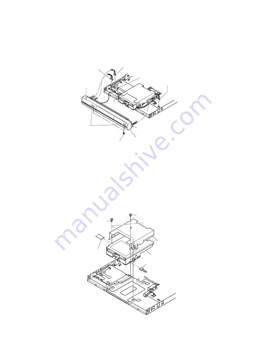
1-1-2. Front Panel
1. Remove the top cover. (Refer to item 1-1-1.)
2. Disconnect three connectors (1).
3. Remove one screw (2) and the earth lead.
4. Remove two screws (3) and four claws, then remove the front panel (4).
Fig. 2-1-2
1-1-3. RAM Drive
1. Remove the front panel. (Refer to item 1-1-2.)
2. Disconnect the flexible cable (1) and connector (2).
3. Remove three screws (3) and the screw (4), then remove the RAM drive (5).
4. Remove the shield cover (6).
Note:
• After replacing, attach the tape (1) to its original position.
Fig. 2-1-3
Connector (1)
Connector (1)
Connector (1)
Screws (3)
Screws (2)
Earth
Front panel (4)
Claw
Claw
Claws
Flexible
cable (1)
Connector (2)
Screws (3)
Screw (4)
RAM drive (5)
Shield cover (6)


