background image

SERVICE MANUAL

TOSHIBA CORPORATION 2008

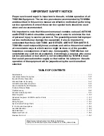
The above model is classified as a green product (*1), as indicated by the underlined serial
number. This Service Manual describes replacement parts for the green product. When
repairing this green product, use the part(s) described in this manual and lead-free solder (*2).

For (*1) and (*2), see the next page.

FILE NO. 810-200801GR

DVD Video Recorder

D-R410KU


Published in Japan,  Jan. 2008 GREEN

0

1

4

R

-

D


R

E

D

R

O

C

E

R


O

E

D

I

V


D

V

D


Summary of Contents for D-R410KU

Page 1: ... number This Service Manual describes replacement parts for the green product When repairing this green product use the part s described in this manual and lead free solder 2 For 1 and 2 see the next page FILE NO 810 200801GR DVD Video Recorder D R410KU Published in Japan Jan 2008 GREEN 0 1 4 R D R E D R O C E R O E D I V D V D ...

Page 2: ...ent of parts is not only confined to manufacture The same green parts used in manufacture must also be used as replacement parts 2 LEAD FREE SOLDER This product is manufactured using lead free solder as a part of a movement within the consumer products industry at large to be environmentally responsible Lead free solder must be used in the servicing and repair of this product WARNING This product ...

Page 3: ... of each way Consequently TOSHIBA has not undertaken any such broad evaluation Accordingly a servicer who uses a service procedure or tool which is not recommended by TOSHIBA must first use all precautions thoroughly so that neither his safety nor the safe operation of the equipment will be jeopardized by the service method selected TABLE OF CONTENTS Specifications 1 1 1 Laser Beam Safety Precauti...

Page 4: ...r 2 front Input level 1 Vp p 75 Ω Jacks RCA jack Video output Output 1 rear Output level 1 Vp p 75 Ω Jack RCA jack S Video input Input 1 rear 2 front Y Iuminance Input level 1 Vp p 75 Ω C color Input level 286 mVp p 75 Ω Jacks 4 pin mini DIN S Video output Output 1 rear Y Iuminance Output level 1 Vp p 75 Ω C color Output level 286 mVp p 75 Ω Jack 4 pin mini DIN Component video output Output 1 rear...

Page 5: ...way from the pickup lens when the diode is turned on Do not look directly at the laser beam CAUTION Use of controls and adjustments or doing procedures other than those specified herein may result in hazardous radiation exposure Location Inside Top of DVD mechanism Do not look directly at the laser beam coming from the pickup or allow it to strike against your skin Drive Mechanism Assembly Laser B...

Page 6: ...ical for safety Replace only with part number specified B In addition to safety other parts and assemblies are specified for conformance with regulations applying to spurious radiation These must also be replaced only with specified replacements Examples RF converters RF cables noise blocking capacitors and noise blocking filters etc C Use specified internal wiring Note especially 1 Wires covered ...

Page 7: ...lug prongs and externally exposed accessible parts RF terminals antenna terminals video and audio input and output terminals microphone jacks earphone jacks etc is lower than or equal to the specified value in the table below Measuring Method Power ON Insert load Z between B earth ground power cord plug prongs and exposed accessible parts Use an AC voltmeter to measure across the terminals of load...

Page 8: ...air to the Flat Pack IC about 5 to 6 seconds Fig S 1 1 2 Remove the flat pack IC with tweezers while applying the hot air 3 Bottom of the flat pack IC is fixed with glue to the BOARD when removing entire flat pack IC first apply soldering iron to center of the flat pack IC and heat up Then remove glue will be melted Fig S 1 6 4 Release the flat pack IC from the BOARD using tweezers Fig S 1 6 CAUTI...

Page 9: ...y one using a sharp pin or wire to which solder will not adhere iron wire When heating the pins use a fine tip soldering iron or a hot air desoldering machine Fig S 1 4 3 Bottom of the flat pack IC is fixed with glue to the BOARD when removing entire flat pack IC first apply soldering iron to center of the flat pack IC and heat up Then remove glue will be melted Fig S 1 6 4 Release the flat pack I...

Page 10: ... Fig S 1 6 Note When using a soldering iron care must be taken to ensure that the flat pack IC is not being held by glue When the flat pack IC is removed from the BOARD handle it gently because it may be damaged if force is applied 2 Installation 1 Using desoldering braid remove the solder from the foil of each pin of the flat pack IC on the BOARD so you can install a replacement flat pack IC more...

Page 11: ... to remove any static electricity that may be charged on the body 2 Ground for Workbench Be sure to place a conductive sheet or copper plate with proper grounding 1 MΩ on the workbench or other surface where the semi conductors are to be placed Because the static electricity charge on clothing will not escape through the body grounding band be careful to avoid contacting semi conductors with your ...

Page 12: ...UTION 2 The DVD MECHANISM DVD MAIN BOARD ASSEMBLY is adjusted as a unit at factory Therefore do not disassemble it Replace the DVD MECHANISM DVD MAIN BOARD ASSEMBLY as a unit NOTE BOARD MEANS PRINTED CIRCUIT BOARD ID Loc No Part Removal Fig No Remove Unhook Unlock Release Unplug Desolder Note 1 COVER TOP D1 6 S 1 2 PANEL FRONT D2 5 L 1 3 L 2 CN2204 1 3 BOARD FRONT D2 4 S 2 CN3002 4 BOARD POWER SWI...

Page 13: ...N2204 Fig D2 5 DVD MECHANISM DVD MAIN BOARD ASSEMBLY See Reference Notes 2 S 4 S 5 S 6 Fig D3 CN101 CN901 CNA02 CN701 M BOARD PLATE EARTH BOARD SUPPORT BOARD SPACERS 6 BOARD POWER SUPPLY S 7 S 7 Fig D4 7 PANEL REAR 8 BOARD AV 9 BRACKET R FRONT S 9 S 8 S 12 S 10 S 10 Fig D5 S 11 DV PLATE EARTH DV JACK ...

Page 14: ...ear be careful not to damage the gear 1 Remove the COVER TOP 2 Rotate the gear in the direction of the arrow manually as shown below until the tray descends 3 Pull the tray out manually and remove a disc View for A Rotate this gear in the direction of the arrow A ...

Page 15: ...izing is completed the DVD recorder exits the Version display mode and turns off the power automatically To move into the Normal mode from the Version display mode press RETURN button on the remote control instead of ENTER button When button is pressed before ENTER button is pressed the DVD recorder exits the Version display mode then the power turns off MODEL NAME FE VERSION BE VERSION TT VERSION...

Page 16: ...own in 1 of Fig d is described as follows 5 After updating is finished the tray opens automatically At this time no button is available 6 Pull out the AC code once then insert it again Fig a Version Up Mode Screen Firmware Version differs depending on the models and this indication is one example Current F W version is displayed Firm Update Mode Please insert a disc ver RD5T H1E Fig b VFD in Versi...

Page 17: ...he presence that the rectifying diode or circuit is shorted in each rectifying circuit of secondary side and replace P1 AV ASSEMBLY if defective FLOW CHART NO 3 When the output voltage fluctuates No Yes Does the secondary side photo coupler circuit operate normally Check the circuit and replace P1 AV ASSEMBLY if defective IC1001 D1007 D1009 Check the circuit and replace P1 AV ASSEMBLY if defective...

Page 18: ...MBLY FLOW CHART NO 7 P ON 5V AUDIO 5V is not outputted Is 5V voltage supplied to the emitter of Q1053 Is the L pulse outputted to the collector of Q1056 Check Q1053 D1060 and their periphery and replace P1 AV ASSEMBLY if defective No No Yes Yes Yes Is the H pulse outputted to Pin 53 of IC1501 Check D1058 D1059 C1060 C1061 L1051 and their periphery and replace P1 AV ASSEMBLY if defective Replace P1...

Page 19: ...58 D1059 C1060 and their periphery and replace P1 AV ASSEMBLY if defective FLOW CHART NO 12 P ON 3 3V is not outputted Is 5V voltage supplied to Pin 1 of IC1503 Replace P1 AV ASSEMBLY No Is 2 8V voltage supplied to Pin 1 of IC1504 FLOW CHART NO 11 P ON 1 8V is not outputted Replace P1 AV ASSEMBLY Check D1056 C1058 and their periphery and replace P1 AV ASSEMBLY if defective Yes Yes Yes No No FLOW C...

Page 20: ...ONT if defective Replace P1 AV ASSEMBLY or P2 DVD MECHANISM DVD MAIN BOARD ASSEMBLY Is the L pulse sent out from Pin 1 terminal of the RE3001 remote control receiver when the remote control unit is activated Is the L pulse signal supplied to the Pin 27 of IC1501 Yes Is 5V voltage supplied to the Pin 2 terminal of the RE3001 remote control receiver Yes Yes No Check EV 5V line and replace P1 AV ASSE...

Page 21: ...01 15PIN IC1301 JK2101 4PIN Continued to A on the next page Yes Are the video signals outputted to each pin of CN1101 Replace P2 DVD MECHANISM DVD MAIN BOARD ASSEMBLY Check the line between each pin of CN1101 and each pin of IC1401 and replace P1 AV ASSEMBLY if defective Are the video signals shown above inputted into each pin of IC1401 Yes No No CN1101 VIDEO Y I P 5PIN CN1101 VIDEO Pr Cr 3PIN CN1...

Page 22: ... VIDEO CVBS Yes VIDEO Y I P Pr Cr Pb Cb Yes No IC1401 VIDEO Y I P 13PIN IC1401 VIDEO Pr Cr 10PIN IC1401 VIDEO Pb Cb 11PIN IC1401 VIDEO CVBS 14PIN IC1401 VIDEO C 15PIN Is the L pulse inputted to Pin 9 10 11 of IC1022 Replace P1 AV ASSEMBLY Check the line between Pin 9 10 11 of IC1022 and Pin 37 of IC1501 and replace P1 AV ASSEMBLY if defective Yes No No Is the video shignal outputted to Pin 15 of I...

Page 23: ...AUDIO L OUT IC1201 2PIN AUDIO R OUT Check each line between each pin of CN1101 and each pin of IC1201 and replace P1 AV ASSEMBLY if defective CN1101 15PIN IC1201 6PIN AUDIO L OUT CN1101 13PIN IC1201 2PIN AUDIO R OUT Are the analog audio signals inputted to each pin of IC1201 Yes No Continued to C on the next page No Do Pin 16 of CN1101 become H level Replace P2 DVD MECHANISM DVD MAIN BOARD ASSEMBL...

Page 24: ...h pin of IC1201 Yes No Check the periphery between Pin 1 7 of IC1201 and the audio terminal JK2201 and replace P1 AV ASSEMBLY if defective IC1022 14PIN AUDIO L OUT IC1022 4PIN AUDIO R OUT Are the analog audio signals outputted to each pin of IC1022 No Yes Is the L pulse inputted to Pin 9 10 11 of IC1022 Replace P1 AV ASSEMBLY Check the line between Pin 9 10 11 of IC1022 and Pin 37 of IC1501 and re...

Page 25: ... ID of RDI VIDEO 13 It is a reply that ATAPI is not readable 14 Cannot write the data after recovering SMALL VMGI 15 Cannot write the data after DVD R Reverse Track 16 An error occurs in Finalize Close 17 An error occurs in Rec Stop Close 18 An error occurs in PCA Full DVD_R 19 Safety Stop occurs during editing 20 High Speed Disc 2 21 The disc is not formatted 5 22 Disc Error has occurred 3 23 The...

Page 26: ... Disc 8 Can not record on this disc Repeat the same operation 37 Access to Memory Area range outside 38 Sector Address is wrong 39 BUP writing error of chapter editing You cannot record more than 49 titles on the disc The maximum is 49 Delete unnecessary titles 43 Its recording capacity has been reached 9 You cannot record more than 254 chapters on the disc The maximum is 254 Delete unnecessary ch...

Page 27: ...2 HDMI CEC OUT 3 3 HDMI CEC IN 27 25 SYS RESET 30 28 SUB RXD 28 26 SUB TXD 26 24 SUB SCLK 29 27 RDY REMOTE SENSOR RE3001 KEY SWITCH 1G 7G 23 17 GRID VFD SEGMENT FL3001 IC3001 VFD DRIVER 28 1 2 CN2204 CN3001 D3202 1080p LED DIN CLK STB BOARD POWER SWITCH BOARD FRONT CN1064 CN3002 POWER SW3010 OPEN CLOSE SW3001 POW SW 2 2 54 15 6 1080p LED 1080i LED 55 16 5 1080i LED 720p LED 56 17 4 720p LED 480p L...

Page 28: ...L LPC LPC MAIN MICRO CONTROLLER MPEG2 AV CODEC TO VIDEO BLOCK DIAGRAM CN1001 SPINDLE MOTOR M CN1002 BOARD RELAY CN301 P ON 3 3V VIDEO Y CVBS VIDEO C IC701 VIDEO DECODER DECODER A D 45 50 U4 W1 W3 Y2 AA1 AA2 A5 B5 B7 C6 C7 D6 D7 DECODER A D 39 44 P3 T3 T5 U2 U3 V1 10 8 13 HDMI SDA HDMI SCL HDMI SDA HDMI SCL YC 0 7 N23 U25 SPDIF SPDIF PCM BCK PCM LRCK PCM SCLK PCM DATA0 P1 D3 D1 N2 M1 N3 M2 VIDEO CL...

Page 29: ...K DIAGRAM VIDEO SW2 CONTROL LOGIC WF1 WF2 WF4 WF5 VIDEO Y CVBS VIDEO C FRONT VIDEO1 VIDEO2 MUTE MUTE C2 C1 REAR 24 VIDEO SW3 LPF LPF MUTE Y2 Y1 1 2 15 IC1021 2 1 4 6dB BIAS 10 TO SYSTEM CONTROL BLOCK DIAGRAM POFF SELECT SW CTL B BUFFER Q1601 C1231 QA01 QA02 DVD MAIN BOARD T M D S DATA2 T M D S DATA2 T M D S DATA1 T M D S DATA1 T M D S DATA0 T M D S DATA0 T M D S CLOCK T M D S CLOCK CNA01 HDMI CONN...

Page 30: ... OP AMP 7 1 13 3 6 2 11 14 4 5 MUTE ON DRIVE Q1202 MUTE ON 9 10 POFF SELECT IC802 AUDIO A D CONVERTER AUDIO A D CONVERTER 7 8 9 13 14 6 SPDIF CN101 CN1051 CN701 CN1101 AIMS MC MD BCK DATA LRCK SYSCLK R CH L CH IN1 IN2 L CH IN1 IN2 R CH SW CTL AUDIO SW2 AUDIO SW1 TO SYSTEM CONTROL BLOCK DIAGRAM OP AMP OP AMP IC1201 2 6 1 7 REC AUDIO SIGNAL PB AUDIO SIGNAL Q1102 Q1513 Q1101 WF6 WF7 JK2104 TO SYSTEM ...

Page 31: ...ircuit is measured using hot GND as a common terminal E7K7ABLP AC1001 AC CORD F1001 1A 250V LINE FILTER L1001 D1001 D1004 Q1003 Q1002 IC1001 ERROR VOLTAGE DET SW BRIDGE RECTIFIER A V F HOT CIRCUIT BE CAREFUL D1063 RECTIFIER D1058 RECTIFIER D1056 RECTIFIER D1051 EV 5V PWSW POW SW Q1001 SW CTL 3 4 1 2 SW CTL RECTIFIER D1054 RECTIFIER Q1053 SW 5V VIDEO 5V AL 30V F1 FL F2 EV 10 5V 3 3V REG IC1503 1 2 ...

Page 32: ... diagram and the parts list Before replacing any of these components read the parts list in this manual carefully The use of substitute replacement parts that do not have the same safety characteristics as specified in the parts list may create shock fire or other hazards Notes 1 Do not use the part number shown on these drawings for ordering The correct part number is shown in the parts list and ...

Page 33: ...ngs were prepared 2 To maintain original function and reliability of repaired units use only original replacement parts which are listed with their part numbers in the parts list section of the service manual 4 Voltage indications for PLAY and REC mode on the schematics are as shown below 5 How to read converged lines 6 Test Point Information A V F This symbol means fast operating fuse Ce symbole ...

Page 34: ...n any models However you cannot mix components under Group A with the ones under Group B You can choose either Group The difference between Group A and Group B is shown below IC1502A IC1502B R3112N191A TR FA FB BU4219G TR PST3619NR Group A Group B C1509A C1509B 0 015 0 1 NOTE BOARD MEANS PRINTED CIRCUIT BOARD ...

Page 35: ...1 11 4 AV 2 4 Schematic Diagram E7K7ASCAV2 NOTE BOARD MEANS PRINTED CIRCUIT BOARD ...

Page 36: ...1 11 5 E7K7ASCAV3 AV 3 4 Schematic Diagram NOTE BOARD MEANS PRINTED CIRCUIT BOARD ...

Page 37: ...1 11 6 E7K7ASCAV4 AV 4 4 Schematic Diagram NOTE BOARD MEANS PRINTED CIRCUIT BOARD ...

Page 38: ...it may cause some components in the power supply circuit to fail NOTE The voltage for parts in hot circuit is measured using hot GND as a common terminal Ce symbole reprèsente un fusible à fusion rapide CAUTION For continued protection against fire hazard replace only with the same type fuse ATTENTION Pour une protection continue les risqes d Incele n utiliser que des fusible de même type Risk of ...

Page 39: ...D DR DB T C 5G 4G 3G 2G 1G 7G 6G a S1 b c d e f g 7G 6G 5G 4G 3G 2G 1G P1 P2 P3 P4 P5 P6 P7 d P8 S1 P9 f g c e a b d f g c e a b d f g c e a b d f g c e a b d f g c e a b d f g c e a b FL3001 MATRIX CHART PM BS CS DR CD VCR DB HDD DVD DTV T C NOTE BOARD MEANS PRINTED CIRCUIT BOARD ...

Page 40: ...m E7K7ASCD1 NOTE BOARD MEANS PRINTED CIRCUIT BOARD The order of pins shown in this diagram is different from that of actual IC101 IC101 is divided into six and shown as IC101 1 6 IC101 6 6 in this DVD Main Schematic Diagram Section 1 NOTE ...

Page 41: ...m E7K7ASCD2 NOTE BOARD MEANS PRINTED CIRCUIT BOARD The order of pins shown in this diagram is different from that of actual IC101 IC101 is divided into six and shown as IC101 1 6 IC101 6 6 in this DVD Main Schematic Diagram Section 1 NOTE ...

Page 42: ...m E7K7ASCD3 NOTE BOARD MEANS PRINTED CIRCUIT BOARD The order of pins shown in this diagram is different from that of actual IC101 IC101 is divided into six and shown as IC101 1 6 IC101 6 6 in this DVD Main Schematic Diagram Section 1 NOTE ...

Page 43: ...m E7K7ASCD4 NOTE BOARD MEANS PRINTED CIRCUIT BOARD The order of pins shown in this diagram is different from that of actual IC101 IC101 is divided into six and shown as IC101 1 6 IC101 6 6 in this DVD Main Schematic Diagram Section 1 NOTE ...

Page 44: ...m E7K7ASCD5 NOTE BOARD MEANS PRINTED CIRCUIT BOARD The order of pins shown in this diagram is different from that of actual IC101 IC101 is divided into six and shown as IC101 1 6 IC101 6 6 in this DVD Main Schematic Diagram Section 1 NOTE ...

Page 45: ...1 11 14 DVD Main 6 7 Schematic Diagram E7K7ASCD6 NOTE BOARD MEANS PRINTED CIRCUIT BOARD ...

Page 46: ...m E7K7ASCD7 NOTE BOARD MEANS PRINTED CIRCUIT BOARD The order of pins shown in this diagram is different from that of actual IC101 IC101 is divided into six and shown as IC101 1 6 IC101 6 6 in this DVD Main Schematic Diagram Section 1 NOTE ...

Page 47: ...1 11 16 BE7K2AF01011A BOARD AV Top View NOTE BOARD MEANS PRINTED CIRCUIT BOARD ...

Page 48: ...PLUS LEAD PIN 3 OF CN1051 WF7 WF7 WF1 PIN 5 OF CN1101 WF5 PIN 3 OF CN1101 PIN 15 OF CN1101 PIN 7 OF CN1101 WF6 WF5 WF4 WF4 WF2 WF6 PIN 1 OF CN1101 BOARD AV Bottom View BE7K2AF01011A NOTE BOARD MEANS PRINTED CIRCUIT BOARD ...

Page 49: ... some components in the power supply circuit to fail NOTE The voltage for parts in hot circuit is measured using hot GND as a common terminal Ce symbole reprèsente un fusible à fusion rapide CAUTION For continued protection against fire hazard replace only with the same type fuse ATTENTION Pour une protection continue les risqes d Incele n utiliser que des fusible de même type Risk of fire replace...

Page 50: ...se it may cause some components in the power supply circuit to fail NOTE The voltage for parts in hot circuit is measured using hot GND as a common terminal Ce symbole reprèsente un fusible à fusion rapide CAUTION For continued protection against fire hazard replace only with the same type fuse ATTENTION Pour une protection continue les risqes d Incele n utiliser que des fusible de même type Risk ...

Page 51: ...1 11 20 BE7H70F01032 BOARD FRONT Bottom View BOARD FRONT Top View NOTE BOARD MEANS PRINTED CIRCUIT BOARD BOARD POWER SWITCH Bottom View BOARD POWER SWITCH Top View BE7K2AF01011D ...

Page 52: ...WF3 C1231 PLUS LEAD WF4 VIDEO Cb Pin 1 of CN1101 0 2V 20μsec WF5 VIDEO Cr Pin 3 of CN1101 0 2V 20μsec SPDIF 1V 0 1μsec WF7 Pin 3 of CN1051 WF2 Pin 7 of CN1101 VIDEO Y 0 2V 20μsec VIDEO C 0 2V 20μsec VIDEO CVBS 0 5V 20μsec NOTE Input COLOR BAR SIGNAL WITH 1KHz AUDIO SIGNAL E7K7AWF ...

Page 53: ...EV 10 5V 1 1 EV 10 5V 2 2 HDMI CEC IN 3 3 GND 4 4 EV 5V 1 1 HDMI CEC OUT 2 2 NU 19 19 EV 2 8V 26 26 EV 2 8V 25 25 NU 20 20 NU 21 21 EV 2 8V 22 22 EV 2 8V 23 23 EV 2 8V 24 24 EV 2 8V 27 27 AL 30V 28 28 F2 29 29 F1 30 30 GND 17 17 GND 18 18 CD LD DVD LD DVD CD LASER DIODE DRIVE PDIC CN701 CN1101 VIDEO Pb Cb OUT 3 1 VIDEO Pr Cr OUT 5 3 VIDEO Y I P OUT 7 5 SUB RXD 30 28 RDY 29 27 SUB TXD 28 26 VIDEO Y...

Page 54: ... CHARTS INNER SW open INNER SW open To disc distinction Power on Yes Yes No No Tray insertion Tray insertion Tray Open button is pressed Tray Open button is pressed Tray ejection Tray ejection SLED moves Push Close INNER SW open Yes No ...

Page 55: ... V T2 3 000 s V2 2 020 V T3 0 050 s V3 2 386 V T4 0 060 s V4 4 302 V T5 0 600 s T6 1 400 s T7 1 600 s T8 0 050 s SLED INNER SW close open Tray insertion direction Tray ejection direction T4 T2 T5 V0 V2 V1 T3 T1 SLED INNER SW close open Tray insertion direction Tray ejection direction V3 V4 T6 T7 T8 ...

Page 56: ...1 14 3 R5NTI Push close 0 08 V 0 02 s Push Close detection Threshold level ...

Page 57: ... Input 28 IN HDMI CEC IN HDMI CEC Signal Input 29 IN RDY Ready Busy communication Control with Main Micro Controller 30 IN P DOWN Power Voltage Down Detector Signal 31 NU Not Used 32 NU Not Used 33 NU Not Used 34 NU Not Used 35 NU Not Used 36 NU Not Used 37 OUT POFF SELECT Power Off Select Signal 38 NU Not Used 39 OUT AUDIO SW2 Audio Input Select Signal 2 40 OUT AUDIO SW1 Audio Input Select Signal...

Page 58: ...d 4 NU Not Used 5 VSS Ground 6 IN VDD 3 3V Power Supply 7 OUT P9 Segment Output 8 P8 9 P1 10 P2 11 P3 12 P4 13 P5 14 P6 15 IN VEE Pull Down Level 16 OUT P7 Segment Output 17 OUT 7G Grid Output 18 6G 19 5G 20 4G 21 3G 22 2G 23 1G 24 IN VDD 3 3V Power Supply 25 VSS GND 26 IN OSC Oscillator Input 27 NU Not Used 28 IN DIN FL Serial Data Input ...

Page 59: ...E C B E C B Note A Anode K Cathode E Emitter C Collector B Base R Reference G Gate D Drain S Source KTC3203 Y AT P KTA1267 GR AT P KTA1271 Y AT P KRC103M AT P KTC3199 BL GR AT P KTA1266 GR AT P MM1637XVBE PQ070XFC1SZF MM1697AJBE 2SK3757 Q KTB1151 Y U P KRC102S RTK P PS2561A 1 W KIA4558F EL P 4052L S16 R 4053L S16 R MN101C77AFT BU4219G TR R3112N191A TR FA R3112N191A TR FB PST3619NR SC16313G MM1509X...

Page 60: ...PRINTED CIRCUIT BOARD A3 CN1701 W1 A1X See Electrical Parts List for parts with this mark Some Ref Numbers are not in sequence DVD MECHANISM DVD MAIN BOARD ASSEMBLY BOARD AV BOARD FRONT BOARD POWER SWITCH BOARD POWER SUPPLY P1 P3 AV ASSEMBLY P2 AC1001 F1001 ...

Page 61: ...1 17 2 E7K7ACEX P1 AV ASSEMBLY AC1001 CN1701 CN1070 CN1051 CN1101 CN1064 F1001 BOARD AV BOARD POWER SWITCH BOARD POWER SUPPLY P1 AV ASSEMBLY ...

Page 62: ...1 17 3 E7K7ACEX P2 DVD MECHANISM DVD MAIN BOARD ASSEMBLY P3 BOARD FRONT DVD MECHANISM DVD MAIN BOARD ASSEMBLY P2 BOARD FRONT P3 CN3001 ...

Page 63: ...1 17 4 E7K7APEX Packing Upper Side Lower Side X20 X22B X22A X5 X1 Unit Some Ref Numbers are not in sequence ...

Page 64: ...oduct through improper servicing Loca tion No TSB P N Reference No Description A1X P000500160 1VM224099B PANEL FRONT E7K7AUD A3 P000483140 1VM323652 COVER TOP E7H70UD W1 P000500330 WPZ0181WJ001 WIRE TIE DV IN CABLE 180MM BLACK ACCESSORIES X1 P000483240 NB323UD REMOTE CONTROL UNIT NB323UD X5 P000457360 WPZ0152TM014 AV CORD WPZ0152TM014 X20 P000500170 1VMN24696 OWNERS MANUAL E7K7AUD X22A P000500180 ...

Page 65: ...0 N78E1EUN DVD MECHANISM DVD MAIN BOARD ASSEMBLY Location No TSB P N Reference No Description P1 P000500210 1VSA17684 AV ASSEMBLY Following part is included in P1 CN1701 P000500240 WX1E7K7A 001 4PIN FFC WX1E7K7A 001 Location No TSB P N Reference No Description C1001 P000493460 CT2E683DC016 ACROSS THE LINE CAP 0 068μF 250V C1002 P000500310 CCD2EMA0E332 SAFETY CAP 3300pF 250V IC1001 P000483270 QPEWP...

Page 66: ......

Reviews: