


1-4-2
DVDN_SN
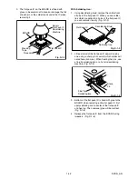
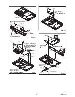
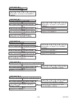
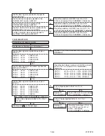
3. The flat pack-IC on the BOARD is affixed with
glue, so be careful not to break or damage the foil
of each pin or the solder lands under the IC when
removing it.
With Soldering Iron:
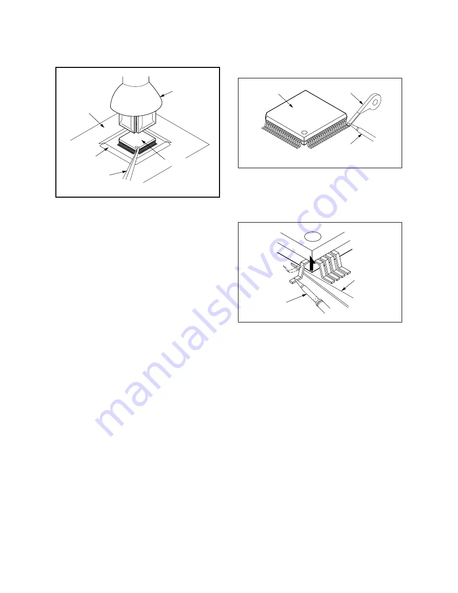
1. Using desoldering braid, remove the solder from
all pins of the flat pack-IC. When you use solder
flux which is applied to all pins of the flat pack-IC,
you can remove it easily. (Fig. S-1-3)
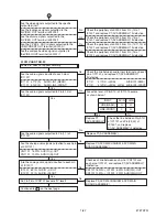
2. Lift each lead of the flat pack-IC upward one by
one, using a sharp pin or wire to which solder will
not adhere (iron wire). When heating the pins, use
a fine tip soldering iron or a hot air desoldering
machine. (Fig. S-1-4)
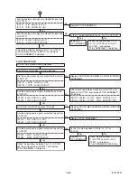
3. Bottom of the flat pack-IC is fixed with glue to the
BOARD; when removing entire flat pack-IC, first
apply soldering iron to center of the flat pack-IC
and heat up. Then remove (glue will be melted).
(Fig. S-1-6)
4. Release the flat pack-IC from the BOARD using
tweezers. (Fig. S-1-6)
Hot-air
Flat Pack-IC
Desoldering
Machine
BOARD
Flat Pack-IC
Tweezers
Masking
Tape
Fig. S-1-2
Flat Pack-IC
Desoldering Braid
Soldering Iron
Fig. S-1-3
Fine Tip
Soldering Iron
Sharp
Pin
Fig. S-1-4
Summary of Contents for D-R410KU
Page 35: ...1 11 4 AV 2 4 Schematic Diagram E7K7ASCAV2 NOTE BOARD MEANS PRINTED CIRCUIT BOARD ...
Page 36: ...1 11 5 E7K7ASCAV3 AV 3 4 Schematic Diagram NOTE BOARD MEANS PRINTED CIRCUIT BOARD ...
Page 37: ...1 11 6 E7K7ASCAV4 AV 4 4 Schematic Diagram NOTE BOARD MEANS PRINTED CIRCUIT BOARD ...
Page 45: ...1 11 14 DVD Main 6 7 Schematic Diagram E7K7ASCD6 NOTE BOARD MEANS PRINTED CIRCUIT BOARD ...
Page 47: ...1 11 16 BE7K2AF01011A BOARD AV Top View NOTE BOARD MEANS PRINTED CIRCUIT BOARD ...
Page 56: ...1 14 3 R5NTI Push close 0 08 V 0 02 s Push Close detection Threshold level ...
Page 66: ......


