6
DeviceNet Module Installation and Operation Manual
Features
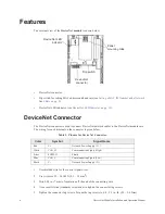
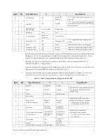
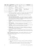
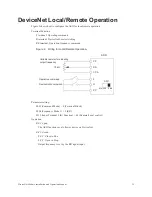
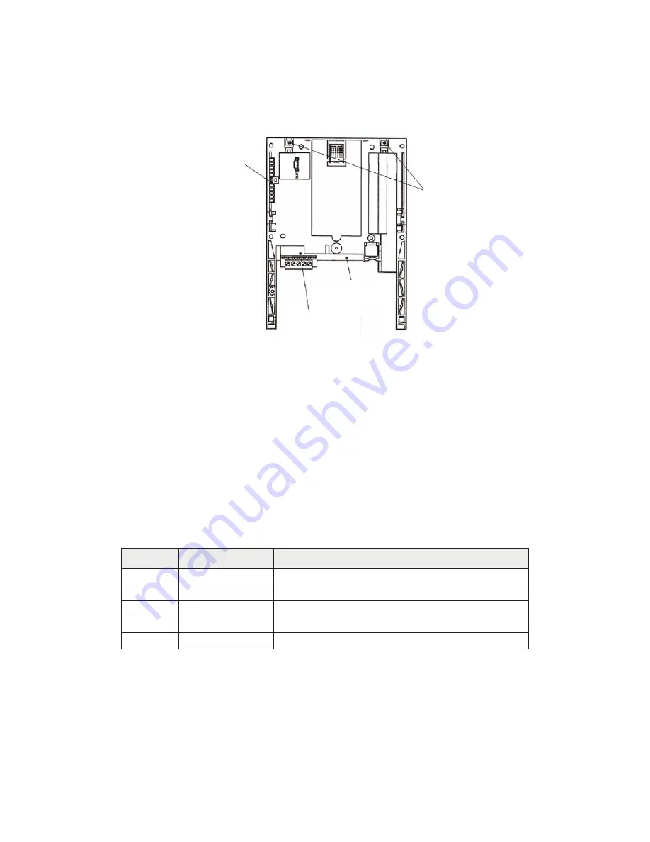
The external view of the DeviceNet module is shown below.
•
DeviceNet connector.
•
Dip switch for setting MAC address and baud rate (see
Setting a MAC ID Number and a Network
).
•
DeviceNet LED indicator (see
DeviceNet LED Indicator on pg. 10
DeviceNet Connector
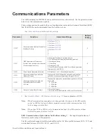
The DeviceNet connector is used to connect DeviceNet network cables to the DeviceNet module card.
The wiring for each terminal on the connector is given below.
Table 1. Pinouts for DeviceNet Connector.
1.
Use shielded wire for the control signal wires.
2.
Use wire size 22 – 16 AWG (0.3 – 1.5 mm2).
3.
Strip 0.28 in. (7 mm) of insulation off the end of the connecting wire.
4.
Use a small slotted (standard) screwdriver to tighten the connector lug screws.
5.
Tighten the connector lug screws. Torque the lug screws to 4.4 – 5.3 in.-lb. (0.5 – 0.6 N•m).
Color
Symbol
Signal Name
Red
V+
Network Power Supply (V+)
White
CAN_H
Communication Signal (High)
Silver
SHIELD
Shield
Blue
CAN_L
Communication Signal (Low)
Black
V-
Network Power Supply (V-)
Panel
mounting tabs
Dip switch
DeviceNet
connector
DeviceNet LED
indicator
Summary of Contents for DEV002Z
Page 1: ...Installation and Operation Manual ASD OPTIONAL DEVICENET MODULE ...
Page 2: ......
Page 55: ......

