8
DeviceNet Module Installation and Operation Manual
Network Connection
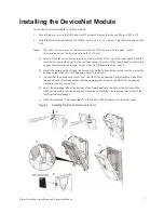
Installation
Do not short-circuit adjacent terminals of DeviceNet module while connecting the wiring.
1.
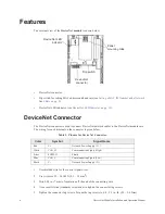
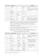
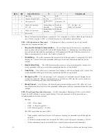
Attach the DeviceNet cable to the DeviceNet connector, and plug in the connector to the DeviceNet
module. Refer to
Recommended cable – Thin branch cables: DeviceNet-specific thin cable.
2.
Set the terminating resistance if needed.
Terminating resistance specification: ¼ W – 121
Ω
, 1% Metal Film resistor.
3.
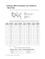
Using the dip switch on the DeviceNet module, set a MAC ID number and a baud rate. Refer to
Setting a MAC ID Number and a Network Baud Rate on pg. 9
.
4.
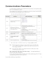
Once all of the parameters are set, cycle the power to the ASD for these changes to take effect.
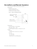
Network Ground
Observe the following precautions when installing a DeviceNet network ground.
•
Do not connect the G/E terminal to a power ground or any other potential noise-producing ground
connection such as the E terminal of the ASD. Connect to a close, clean ground to provide RF
termination of the DeviceNet cable.
•
Do not make connections to unstable grounds (paint-coated screw heads, grounds that are subjected
to inductive noise, etc.).
The DeviceNet network should be earth grounded at one location only to prevent ground loops. No
significant current flow between V- and earth ground may occur via any device other than a power
supply under normal operating conditions. This specification is from the ODVA DeviceNet
specification.
Power Tap
Isolation
Barrier
Power Supply
Node
Node
Node
Node
Node
+
-
Summary of Contents for DEV002Z
Page 1: ...Installation and Operation Manual ASD OPTIONAL DEVICENET MODULE ...
Page 2: ......
Page 55: ......


