1600/2000/2500 ADJUSTMENT ITEMS
1 - 80
December 2000 © TOSHIBA TEC
7. Apply the screw lock paint to all the screws se-
cured.
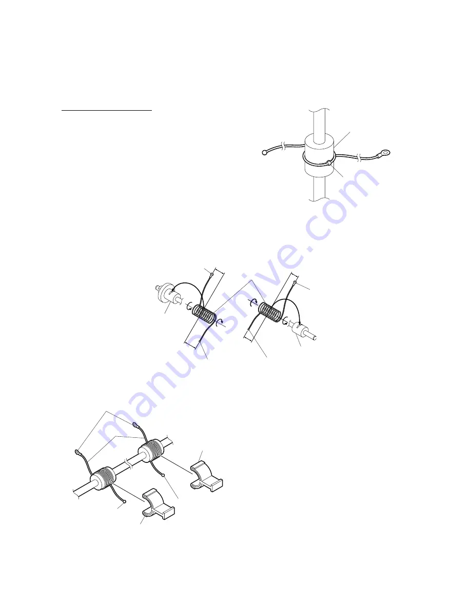
(b) Installing the wire to the pulleys
Winding the wire on pulley.
1. Fit the
φ
3.2 spherical terminal at the center of
the wire into the hole in the wire winding pulley.
Wind up the wires on the front and rear sides,
respectively, as shown below and secure the
wire with the clip jig to prevent it from getting
loose.
Fig. 1-8-17
[Rear Side]
[Front Side]
Fig. 1-8-18
Fig. 1-8-19
Pulley
Ball terminal
Spherical
terminal
Wire
Scanner drive shaft
Scanner drive shaft
Spherical
terminal
Hook
Hook
5½
turn
s
4½
turn
s
4½
turn
s
Hook
Ball terminal
Wire
Clip jig
Clip jig
Ball terminal
065-10
065-01
065-11
5½
turn
s


