background image


46 


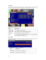
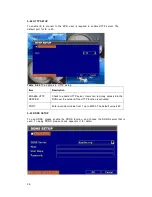
5-8.4 SPOT SETUP 


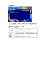
The  DVR  has  two  modes  of  video  output;  one  is  main  video  output,  the  other  is  spot  video 

output. SPOT setup is for controlling the order of channels the system cycles through in SPOT 

mode. User can monitor every channel in the SPOT mode. 


Table  5-8.7 

The  options  in  buzzer  &  relay  setup 

Item 

Description 

SPOT MODE 

Channels display in spot for three different modes


MANUAL

Select channels to display manually. 

SEQUENCE

Auto-sequence for all channels in order. 

EVENT

Display channels with event occurred. 

INTERVAL 

(SECONDS) 

The duration time in seconds for the interval between channels under 

SPOT mode. 

SKIP VIDEO LOSS 

CHANNEL 

Whether to skip channels without video signal. 


Summary of Contents for DVR

Page 1: ...1 This document contains preliminary information and subject to change without notice 4 8 16 Channel H 264 DVR User Manual ...

Page 2: ...s Operation of this equipment in a residential area is likely to cause harmful interference in which case the user will be required to correct the interference at their own expense CE Mark This product is marked with the CE symbol and indicates compliance with all applicable EEC directives Warning To prevent fire or shock hazard do not expose the unit to rain or moisture This symbol alerts the use...

Page 3: ... 1 Record Setup 20 5 1 1 Quality Frame Rate Setup 21 5 2 Event Setup 22 5 2 1 Motion Setup 23 5 2 1 1 Motion Area Setup 24 5 2 2 Sensor Setup 25 5 3 Schedule Setup 26 5 3 1 Schedule Record Setup 27 5 3 2 Holiday Setup 27 5 4 Camera Setup 28 5 5 Account Setup 30 5 5 1 Permission Setup 31 5 6 Networking Setup 32 5 6 1 Networking Setup 33 5 6 1 1 DHCP 34 5 6 1 2 LAN 35 5 6 1 3 ADSL 35 5 6 2 HTTP Setu...

Page 4: ...or Symbian System 61 8 1 1 Mobile Application Installation 61 8 1 2 Mobile Application Operation 61 8 1 2 1 Add New Login DVR 61 8 1 2 2 Logging Onto the DVR 62 8 1 2 3 Modify the Login Information of DVR 63 8 1 2 4 Delete the Login Information of DVR 63 8 1 3 Live Monitoring Operation 63 8 1 3 1 Scroll the Image 63 8 1 3 2 Image Quality Setup 64 8 1 3 3 Channel Display 64 8 1 3 4 Size of Image 64...

Page 5: ...4 2 View Event Logs 80 9 4 3 Main Display 80 9 4 4 Audio Control 81 9 4 5 eMap Display 81 9 4 3 PTZ Control 83 9 5 Local PC Video Record and Information 83 9 6 Playback Video 84 9 6 1 Remote Play 84 9 6 2 HDD Playback 85 9 6 3 File Playback 86 9 6 4 Event Playback 87 9 6 5 Snapshot Data 88 9 6 6 Recording Data 88 APPENDIX I HARD DISK INSTALLATION 89 APPENDIX II DDNS SETUP 91 APPENDIX III TROUBLE S...

Page 6: ...nnector for 16CH DVR only 10 Camera 4 for 4CH DIY kit only 11 DIY cable 4 for 4CH DIY kit only CHAPTER 2 PANEL LOCATION 2 1 4 8 16 CH DVR FRONT PANEL CONTROL 4CH Front Panel 8 16CH FRONT PANEL 3 Backup 4 PIP display 5 Zoom 6 Sequence Display 7 Search 8 ESC 9 Menu 1 USB 2 LEDs 10 Record 11 Pause 12 Play 13 Rewind Left 14 Fast Forward Right 15 Slow Forward Up 17 Enter Mode 16 Stop Down ...

Page 7: ...ay menu 10 REC Start or stop recording 11 PAUSE In PLAYBACK mode press to pause playback 12 PLAY Play back in normal speed 13 In SETUP mode press to reduce value In PLAYBACK mode press to play rewind 14 In SETUP mode press to increase value In PLAYBACK mode press to play forwards 15 SLOW In SETUP mode press to move cursor up In PLAYBACK mode press to slow down 16 DOWN STOP In SETUP mode press to m...

Page 8: ... 11 ALARM IN CH5 12 ALARM IN CH6 13 ALARM IN CH7 14 ALARM IN CH8 8 LAN Network port 9 NTSC PAL SWITCH Switch between NTSC and PAL format 10 SPOT MONITOR BNC port to display full screen image of all installed cameras in sequence 11 Power DC12V Socket for a DC 12V input 12 EXTERNAL I O 16CH DVR only 1 GND 2 GND 3 RS 485 B 4 RELAY NO 5 RS 485 A 6 RELAY COM 7 GND 8 RELAY NC 9 GND 10 GND 11 ALARM IN CH...

Page 9: ... Schedule Method By resolution fps and quality Setup fps and quality separately for normal and event recording 3 SATA DEVICE Internal Storage 2HDD 8CH 16CH 1 HDD 4CH Capacity External Storage E SATA 8CH 16CH model only Type SATA SATAⅡ compatible 4 ALARM Sensor Input 16 16CH 8 8CH 4 4CH Alarm Out 1 Relay output Motion Detection Available per each camera Multi detection level 5 CONNECTIONS Video Inp...

Page 10: ...ax client Supporting multi client 5 clients accessible 12 OTHERS OS Embedded Linux Multi Task Pentaplex Live Record Playback Network Backup Control Device Front Keys Remote Control Virtual Keyboard Mouse AP Software PC Viewer Direct viewing of DVR s HDD on PC Numbers of event list 9999 Table 3 1 352 x 240 240fps 16CH 8CH 120fps 4CH 720 x 240 120fps 16CH 8CH 60fps 4CH NTSC 720 x 480 60fps 16CH 8CH ...

Page 11: ...signal and have some related operations under LIVE mode This paragraph describes the IR remote control mouse operation and on screen graphical icons under LIVE mode Graphic icons to show each camera status See Section 4 1 2 Graphic icon to show network status Current date and time Playback the video stored in the DVR See Section 4 2 Use PTZ function to move the camera See Section 4 3 Graphic icons...

Page 12: ...play 10 LOCK Enable Disable the keypad function on the front panel the remote control and the mouse 11 PLAY Start playing back the most recently recorded segment 12 T SRH Display search menu 13 Up Down Left Right ENTER Direction and ENTER buttons 14 MENU Display setup menu 15 ESC Return to the previous mode 16 Z Z PTZ zoom in out 17 IRIS PTZ iris open close 18 F PTZ focus in out 19 OSD Turn on off...

Page 13: ...de Icon Description Icon Description Motion detected on the channel Video loss detected on the channel Sensor triggered on the channel number No event happening Table 4 1 4 Description of on screen graphical icons in LIVE mode Icon Description Icon Description Recording is on Remote user currently logging into DVR Audio is on Audio is off Timer recording is on Red Timer is set and recording has be...

Page 14: ... Play back at slower speed The speed will be slowed to 1 2 1 4 1 8 1 16 by each pressing of the button till the slowest limitation of 1 16 of the normal speed Current playback speed is shown in the upper center of the screen Fast rewind Each press increases the speed to the next level There are six kinds of speed 2x 4X 8X 16X 32X and 64X Fast forward Each press increases the speed to the next leve...

Page 15: ...cription SLOW Move PTZ up Move PTZ down Move PTZ to the left Move PTZ to the right ZOOM PTZ zoom in ZOOM PTZ zoom out FOCUS PTZ focus in FOCUS PTZ focus out IRIS PTZ iris open IRIS PTZ iris close PRESET NUMBER Setup the Preset location P ress PRESET key first then two digit number DVR will set the current PTZ location at entered preset number PLAY NUMBER Go to Preset location Press PLAY key first ...

Page 16: ... zoom out PTZ focus in PTZ focus out PTZ IRIS open PTZ IRIS close Below functions need support from specific PTZ manufacturer Please check user manual of your PTZ for more details AUX 1 AUTO key Number Key 1 AUX 2 AUTO key Number Key 2 AUX 3 AUTO key Number Key 3 AUX 4 AUTO key Number Key 4 AUX 5 AUTO key Number Key 5 AUX 6 AUTO key Number Key 6 AUX 7 AUTO key Number Key 7 AUX 8 AUTO key Number Ke...

Page 17: ...Please also refer to the CD for video tutorial which will help you get on hand in shortest time Login To enter the main menu and set up DVR log in account and user password are required The default password of the administrator is 123456 Please check the ACCOUNT SETUP for related setup of other log in users Table 5 0 1 Definition of the virtual keyboard Item Description Switch between capital and ...

Page 18: ...rmined by Record Type in section 5 1 1 If the record is set Off the record mode will be determined by the schedule setting Setup This provides the setup menu for users This includes the main menu for configuration search setup backup setup and PTZ setup Setup Move your mouse here to setup Record On Off Playback See Section 4 2 Display Setup Full Screen Display Quad Display Click here to setup Main...

Page 19: ...p as well as schedule setup Table 5 0 2 The operation of remote control under the setting menu Item Description Switch to different options under the one item Switch to different items MENU Save setup and back to LIVE mode BK UP ESC Back to Upper level of menu without saving ENTER Enter the menu or display virtual keyboard Record Setup Event Setup Schedule Setup Camera Setup Account Setup Network ...

Page 20: ...Motion and Schedule Sensor as well as 2 enable these function in the event setup For detail please refer to Section 5 2 1 on motion detection and Section 5 2 2 for sensor Table 5 1 1 The options in record setup Item Description HDD FULL Select STOP to stop recording or OVERWRITE to reuse the HDD when HDD is full STOP Stop recording when HDD is full OVERWRITE Start to overwrite that begin from the ...

Page 21: ...mal recording and event recording type 5 1 1 QUALITY FRAME RATE SETUP User can adjust the resolution for the cameras User can also adjust the quality as well as the frame rate of each individual camera FPS stands for Frames Per Second and as the value increase the video will be smoother Table 5 1 2 The options in quality frame rate setup Item Description RESOLUTION Choose record resolution from CI...

Page 22: ...arm input from alarm sensors Users can adjust the alarm duration in other word the record time for the detected event Table 5 2 1 The options in event setup Item Description ALARM DURATION SECONDS Set up alarm duration in seconds Drag the white bar or press to adjust value MOTION SETUP Enter to set up motion detection SENSOR SETUP Enter to set up sensor detection ...

Page 23: ...ION POPUP Check the box to enable disable popup screen function for all channels When motion is detected in LIVE mode the detected channel image will pop up in full screen display 1 4 You can setup independently for each channel SELECTED CHANNEL TURN Check the box to enable disable motion detection for each channel OBJECT SIZE Drag the white bar or press to set up Object Size from value 1 to 15 fo...

Page 24: ...creen as detection area STATUS Switch between SELECT and DESELECT for cursor dragging function ENTER Press to function on the selected area with assigned status MENU Press to save the setup and leave ESC Press to cancel the setup and leave The blue background is the selected region for motion detection Select The red background is the region that cannot detect motion Deselect Press Select All to s...

Page 25: ...n for all channels SENSOR POPUP Check the box to enable disable popup screen function for all channels When sensor is detected in LIVE mode the detected channel image will pop up in full screen display SENSOR POLARITY Click or press to select between HIGH LOW voltage for triggering sensor detection or OFF to turn off the sensor for each channel LOW Polarity Sensor has not been triggered When conne...

Page 26: ... in schedule setup ITEM DESCRIPTION PAGE Click or press to select Page Each page provides 10 schedules for setup 5 pages in total SCHEDULE To enable each schedule please mark on them To adjust the content of each scheduling please click on the option See 5 3 1 HOLIDAY SETUP Enter to setup holiday up to 50 days other than weekends See 5 3 2 VIEW EVENT SETUP View Normal Motion Sensor Setup Green The...

Page 27: ... click Enable to activate the schedule 5 3 2 HOLIDAY SETUP Since holidays are different by different country and region you can setup the holiday of your location accordingly The orange days are the selected holidays The maximum number of days you can select are 50 days Click to choose different months Click to enable the schedule Click to select the day as holiday ...

Page 28: ...hannel MASK Check the box to enable disable mask function for LIVE mode BRIGHTNESS Drag the white bar or press to adjust the brightness of your camera from value 1 to 255 The default value is 128 CONTRAST Drag the white bar or press to adjust the contrast of your camera from value 1 to 255 The default value is 128 SATURATION Drag the white bar or press to adjust the saturation of your camera from ...

Page 29: ...name of each channel To ensure the name is read easily it is suggested to use less than 30 characters VOLUME Select to adjust the audio input volume in live mode for several channels under LIVE mode and recording mode 4 Channel DVR CH1 8 16 Channel DVR CH1 CH4 Note The audio recorded is tied with the camera For example Audio 1 is recorded with the video in Camera 1 ...

Page 30: ...rs by setup user name password permission list and remember to click on the No to activate the account Table 5 5 1 The options in account setup Item Description Function Setting Auto Logout Key Lock Key lock Key unlock X AUTO LOCK Disable X X NO Check to activate the user s account PASSWORD Enter to set up password for each user Password MUST be set up to 8 characters mixed by letters and numbers ...

Page 31: ...etween channels etc If you need to enter the setup menu search menu backup menu record etc you will need to enter user account and password In the status key lock automatically remote control and mouse can t function before entering the user account verified password Enable the function X Disable the function 5 5 1 PERMISSION SETUP The Account Setup is set to provide individual user maximum of 4 u...

Page 32: ...l notification Table 5 6 1 The options in networking setup Item Description CONNECT TYPE Setup mode for network connection DHCP LAN ADSL HTTP SETUP Enter to set up HTTP for remote access into DVR DDNS SETUP Enter to enable disable DDNS function and set up MAIL SETUP Enter to enable disable Email notification and setup There are up to 10 email addresses can be notified with different event options ...

Page 33: ...IP Static IP Connection Static IP is considered as a fixed IP assigned by ISP Public IP or IP share device Virtual IP DVR connecting to static IP needs to be assigned IP address Gateway and Subnet mask Public Static IP LAN port for Router Eg IP 61 201 78 21 Mask 255 255 255 248 Public Static IP Eg IP 61 201 78 22 Mask 255 255 255 248 Public Static IP WAN port Eg IP 61 201 78 21 Mask 255 255 255 24...

Page 34: ...d from one ISP supplier Please set up username and password for ADSL connection 5 6 1 1 DHCP If the DHCP option is used for DVR network connection an IP address is assigned by the DHCP server automatically Public Static IP WAN port Eg IP 61 201 78 21 Mask 255 255 255 248 Private Dynamic IP LAN port Eg IP 192 168 1 20 assigned by Router Mask 255 255 255 0 Dynamic IP Configuration IP 192 168 1 1 Mas...

Page 35: ...P SUBNET MASK Enter IP address of Subnet Mask provided by ISP GATEWAY Enter IP address of Gate way provided by ISP DNS Enter DNS address provided by ISP Note The correct DNS address must be entered for DDNS function 5 6 1 3 ADSL Select ADSL for network connection the following information including user name and password is required Table 5 6 3 The options in ADSL setup Item Description USER NAME ...

Page 36: ...scription ENABLE HTTP SERVER Check to enable HTTP server Users can remotely access into the DVR over the network if the HTTP function is activated PORT Enter a valid port value from 1 up to 65000 The default value is 80 5 6 3 DDNS SETUP To use DDNS please enable the DDNS function and choose the DDNS server that is used To apply DDNS please check appendix II for detail ...

Page 37: ...in related information including the SMTP server user name password and email of the sender as well as the receiver s email Table 5 6 6 The options in mail setup Item Description ENABLE E MAIL NOTIFICATION Check the box to enable disable E mal Notification function SMTP SERVER Enter to set up SMTP server name USER NAME Enter to set up user name PASSWORD Enter to set up password SENDER E MAIL Enter...

Page 38: ... ENABLE MSN NOTIFICATION Check Uncheck to enable disable MSN notification MSN ACCOUNT MSN account to be logged in PASSWORD Account password to log into MSN MSN RECEIVER MSN account to receive event notification messages This is the MSN account to receive the notification on an event This is the MSN account and the password to send the notification on an event ...

Page 39: ...DVR Table 5 7 1 The options in PTZ and RS485 setup Item Description ENABLE PTZ Click the box to enable disable PTZ function for each channel PROTOCOL Set up the protocol of PTZ cam The supported protocol are PELCO P PELCO D KND LI LIN PTZ ID Click or press to set up PTZ ID The valid ID value is from 1 to 64 BAUD RATE Select baud rate for PTZ from 2400 4800 9600 ...

Page 40: ...f DVR will be shown when users login from remote access DVR LOCATION The location of DVR will be shown when users login from remote access LANGUAGE Click or press to select OSD language from English Chinese Greek Italian Japanese Portuguese Spanish German French Russian or Polish AUTO SEQ INTERVAL SECONDS Click or press to setup duration time in seconds for the interval between channels under Auto...

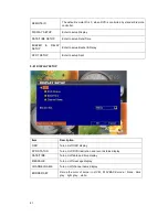
Page 41: ...setup Buzzer Relay SPOT SETUP Enter to setup Spot 5 8 1 DISPLAY SETUP Item Description OSD Turn on off OSD display DVR STATUS Turn on off DVR illustration and record status display DATE TIME Turn on off date and time display MESSAGE Turn on off message display CHANNEL NAME Turn on off channel name display BORDER SET Set up the color of border in LIVE1 PLAYBACK mode black dark grey light grey white...

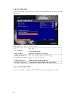
Page 42: ...2HOURS 24HOURS DATE FORMAT MM DD YY DD MM YY YY MM DD DATE TIME POSITION Choose the position of time and date display CHANGE DATE TIME Setup time and date of DVR TIME ZONE SETUP Setup GMT and daylight saving time INTERNET TIME SETUP Setup automatic synchronization with internet server 5 8 2 1 CHANGE DATE TIME Users are allowed to setup date and time of DVR manually according to your local time ...

Page 43: ...e your time zone and activate daylight saving time function according to your DVR location Table 5 8 4 The options in time zone setup Item Description SELECT TIME ZONE Enter to modify GMT from GMT 13 to GMT 13 DAYLIGHT SAVING TIME Turn on off daylight saving time ...

Page 44: ...setup Item Description AUTOMATIC SYNCHRONIZATION Check to enable DVR automatic synchronization function Effective by this option selected DVR will automatically synchronize the time upon rebooting or by every 24 hours after booting UPDATE NOW Date and time show on DVR will immediately correspond with those in internet server ...

Page 45: ...et relay signal to be Normal Close N C or Normal Open N O BUZZER DURATION Set up the duration from 1 999 seconds ALARM BUZZER Enable disable buzzer operation when the alarm is triggered for sensor motion and Vloss Video Loss ALARM RELAY Enable disable the signal to be sent to the RELAY OUT blocks when the alarm is triggered for sensor motion and Vloss ...

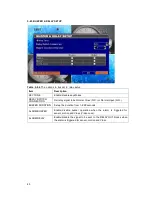
Page 46: ... the SPOT mode Table 5 8 7 The options in buzzer relay setup Item Description SPOT MODE Channels display in spot for three different modes MANUAL Select channels to display manually SEQUENCE Auto sequence for all channels in order EVENT Display channels with event occurred INTERVAL SECONDS The duration time in seconds for the interval between channels under SPOT mode SKIP VIDEO LOSS CHANNEL Whethe...

Page 47: ...f HDD that installed in DVR Check the HDD you would like to initialize then press START HDD initialization is succeeded when the status shows SUCCEED USB INITIALIZATION Clean up all data on USB Enter USB initialization and press YES to clean up all data on your USB The initialization is done when it s showed SUCCEED SYSTEM RECOVERY Restore system default values RESET SYSTEM EVENTS Reset all the re...

Page 48: ...e DVR through USB Please stop recording and backup setup configuration before upgrading The system will reboot automatically when the upgrade is completed Notice DO NOT TURN OFF POWER OR UNPLUG USB DEVICE DURING UPGRADE PROCESS as it may cause incomplete firmware upgrade and damage to the DVR ...

Page 49: ... the screen will display NETWORK DISCONNECT MAC ADDRESS MAC Address of DVR HDD VOLUME The capacity of HDD HDD USED RATE Percentage of space used on HDD HDD STATUS Shows HDD status USING means the HDD is being used for recording now GOOD BAD means the HDD has a known unknown format for the DVR Note Please initialize your newly installed HDD before using it otherwise it can be recognized as BAD by D...

Page 50: ...e or iCMS Table 6 1 1 The options in backup setup Item Description FROM The start time of backup file TO The end time of backup file DEVICE Select USB etc as the backup device FREE SPACE The available space in your backup device REFRESH Recalculate the available space of backup device CALCULATE Calculate the size of backup file START Start backup operation Be sure to calculate the size of backup f...

Page 51: ...very event will be shown as a list and user can choose to playback a certain event In time search the user can specify a certain time range to playback Table 6 2 1 The options in search setup Item Description EVENT SEARCH Press to enter event search menu TIME SEARCH Press to enter time search menu ...

Page 52: ...o playback the recording data Item Description CRITERIA Setup conditions of event search PAGE Convert pages of events DATE TIME Date time when event occurred Event type defined as following VLOSS Video Loss MOTION Motion Detected SENSOR Sensor Detected REMOTEIN user log in over the network REMOTEOUT user log out over the network POWER ON System Rebooting KEY LOCK System key are locked KEY UNLOCK S...

Page 53: ... a lot Therefore you can facilitate event sorting by setting up CRITERIA Setup Start time End time and Event type for event search and the search result will be limited to this specific period of time Only checked events and channels will be sorted in event search as well ...

Page 54: ...k according to the date you selected Calendar will be shown by using mouse to click on YEAR and MONTH Click DATE to display recording time of that specific date with time bar You can change time hour minute second or click on a specific time of time bar by mouse then press YES DVR will playback the selected recording data Pull the time bar with a mouse to select a specific time region Press Enter ...

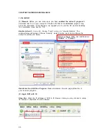
Page 55: ...ance See Section 7 2 Enable Active X In your IE choose Tools and go to Internet Options The window below will appear Choose Security select Custom level and configure the activeX conditions as below Deactivate the Anti Virus Program Please deactivate the web page protection in your antivirus program 2 Login DVR with IE Step One Enter the IP address of DVR in IE browser Here you may choose to setup...

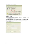
Page 56: ...name and password Default user name is admin and password is 123456 Other related setup about user account and password please check 5 5 ACCOUNT SETUP Step Three Please enter information of login DVR IP port user name and password or choose PLAY RECORDED FILE to open backup files in your PC Step Four You ve logged into the DVR ...

Page 57: ...tware can be found inside the CD 1 Download From The Internet Step One Enter the IP address of DVR in IE browser Note This IP is only for reference Please setup your local IP Step Two Below windows will be shown up Please enter the user name and password Default user name is admin and password is 123456 Other related setup about user account and password please check 5 5 ACCOUNT SETUP Step Three C...

Page 58: ...net click on the program DVRemoteDesktop exe to run Step Five If you choose to run the software Start window will be shown up Please enter information of login DVR IP Port Username and Password or choose Play Recorded File to open backup files in your PC The default username and password is admin 123456 ...

Page 59: ...nts for software Table 7 3 1 Toolbar of AP software FILE RECORD TO LOCAL Record data to your PC including LIVE and Playback FILE PLAY RECORDED FILES Play recorded files irf FILE EXIT ALT F4 Close the AP software EDIT CHANNEL NAME F2 Edit the channel name of your DVR including font size italic and boldface of characters EDIT RESET CHANNEL NAME Reset channel name back to default VIEW HIDE CAPTION ME...

Page 60: ...60 Table 7 3 2 System Requirements for AP software CPU Intel Pentium 4 above OS Microsoft Windows Vista Windows XP SP2 above RAM 512M above OTHERS DirectX 9 0 above ...

Page 61: ...TALLATION Please follow the steps cited below to perform the mobile device surveillance function Step 1 Please download the files DVRH264 jar and DVRH264 jad in the CD that is packed with DVR through Bluetooth or USB cable to your mobile phone The files are in 3G_Software Mobile Symbian You can also download files from the manufacturer s website to your mobile phone Step 2 Install the application ...

Page 62: ...log in 2 A confirmation message might show up for network charge before connection The fee rate will depend on the telecom company and package fee you go with 3 Network connectivity will take some time It ll be affected by networking environment and bandwidth flow Live image will show up after a successful connection PS The Live cannot be displayed in your mobile when the recording is off in local...

Page 63: ...be used to remove the DVR information if it is no longer useful Select the DVR on the name list then choose DELETE 8 1 3 LIVE MONITORING OPERATION This paragraph describes some operation under LIVE monitoring mode in your mobile device 8 1 3 1 SCROLL THE IMAGE You can use the keypad on your mobile device to scroll the image if it s oversized Table 8 1 1 Keypad Action KEY ACTION 2 Scroll Up 4 Scrol...

Page 64: ...channels of your DVR in list for you to choose PS The Live cannot be displayed in your mobile when the recording is off in local DVR 8 1 3 4 SIZE OF IMAGE The screen size of different mobile device can be really different You can select SIZE under the MENU to choose from ORIGINAL or FIT SCREEN to resize the display image Table 8 1 2 Adjust Size of Image Item Description ORIGINAL The image will be ...

Page 65: ...ALARM This application not only allows you to remotely monitor t hrough mobile device but receive the alarm that has been triggered by events such as motion detected sensor triggered and Vloss Graphical icons below will be shown on the status Motion detected Sensor triggered Video loss Select the ALARM under the MENU to switch this function on or off ...

Page 66: ...ase follow the steps cited below to perform the mobile device surveillance function on your mobile device mobile phone PDA etc Step 1 There are different software for PDA mobile phone PDA phone Please download the H264Pocket CAB in the CD in path 3G_Software PDA You can also download files from the manufacturer s website to your phone Mobile Phone Please download all the files in 3G_Software Mobil...

Page 67: ...escription ADD Add login DVR Enter DVR s name IP address port account user password Then press OK LOGIN Login DVR Choose the DVR that you d like to log in and press OK PS The Live cannot be displayed in your mobile when the recoding is off PS Network connectivity will be affected by networking environment and bandwidth flow The fee rate will depend on the telecom company and package fee you go wit...

Page 68: ... the size as full screen Fit resize the image to fit the screen QUALITY Quality Change the quality of image Please note the better quality the slower data transfer rate STATUS BAR Status Bar Graphical icons indicated below will be shown on the status bar if there is event such as motion detected sensor triggered and video loss detected on any channel You can also uncheck the STATUS BAR to deactiva...

Page 69: ...ER SYSTEMS For other 3G mobile system like 1 Apple System including iPhone and iPod Touch and 2 Blackberry System etc no installation is required Please go to the website http DVR IP address jpeg html and you will be able to run Live monitoring ...

Page 70: ...iefly introduce the software interface 9 3 9 5 Introduce the environment 9 1 CMS INSTALLATION Please check if your PC reach the following requirements to make sure it works properly Intel Pentium 4 processor or equivalent Microsoft Windows Vista Windows XP Windows 2003 Server 512MB memory above 500M requested for group DVR connection and 180M for single DVR 20MB HD space Recording and image captur...

Page 71: ...hange installation path if needed To check available space on hard disk please select DISK COST then please select NEXT to go to the next step 3 The CONFIRM INSTALLATION window shows up Select NEXT and the installation starts ...

Page 72: ...72 4 Select CLOSE to finish installation when the INSTALLATION COMPLETE window shows ...

Page 73: ... groups and events See 9 4 REMOTE SURVEILLANCE MANAGEMENT for detail 3 MAIN DISPLAY Live image display area See 9 4 REMOTE SURVEILLANCE MANAGEMENT for detail 4 PC INFORMATION AND CONTROL Information about local PC s hard disk volume recording etc See 9 5 LOCAL PC INFORMATION AND CONTROL for more detail 5 DISPLAY MODES Display modes supported by CMS Note that group setup is required to use the disp...

Page 74: ...ct to DVR please refer to 9 3 2 3 Group up your DVRs and arrange the cameras Assume you have one or more DVRs connected You can arrange your cameras on a specific channel on the screen and save this arrangement as a group name In this way you can manage the cameras very easily For detail please refer to 9 3 3 4 Including additional information If you want to include a map or some reference informa...

Page 75: ...tor should assign proper authority to each user These user accounts can be deleted or edited later on Select OK to save the setup After the account and password has been setup the next time user opens the ICMS when the login window appears the user can type in the newly registered username and password to login ICMS Icon Description Add a user account The default authority is with none permission ...

Page 76: ...er name and password refers to the account setup in the DVR To register a new account please refer to Section 5 5 2 Each DVR setup slot is only for an individual user If you have more than one user connecting to the same DVR please add a DVR setup slot for each user Icon Description Add a DVR for a specific user Delete a DVR for a specific user Each slot is only for a user Type in the user ID and ...

Page 77: ... like to include in the group To include all channels of a DVR just check the DVR Icon Description Add a group for a specific user Delete a DVR for a specific user 4 Click OK to return to the previous window 5 Select a display mode 6 Drag a channel from the lower left panel into the main display to a preferred location Or change the channel location in the main display by mouse dragging 7 You can ...

Page 78: ...ll show in the right panel 3 Drag channels in the left lower corner onto the picture to any position 4 To delete a channel already on the picture right click the channel and click REMOVE 5 Click OK to save 3 The chosen cameras will appear in this window Drag them to the right and place them 4 The cameras are arranged Note that for different number of channel display you can arrange cameras in a di...

Page 79: ...k on a connected DVR will show its image on the main display On the Group list double left click on a group will show live image from the channels of the group in the main display Left clicking on a connected DVR will expand collapse status of its all channels as below Icon Description Video Loss Motion Detected Sensor Triggered Icon Description View list of logged in DVR Group 1 Click here and th...

Page 80: ...the order of Remote in Remote out Video Loss Motion Sensor Others Power Reset Key Lock Key Unlock HD Full 9 4 3 MAIN DISPLAY The main display area is where the live image of DVR is shown You can drag to change the location of screen for each channel and turn on off audio signal with mouse click ...

Page 81: ...n please note there can allow only one channel s audio signal to be on at one time 9 4 5 eMAP DISPLAY In Live mode pressing will bring the e MAP drag down menu If the channel has been set up to use e MAP the menu will show all the e MAP titles that have been entitled to this channel otherwise NO eMAPS will be shown Please check 9 3 4 eMAPSET UP for setup information ...

Page 82: ...82 When you choose the eMap the camera channel displays will be shown on the eMap The camera display ...

Page 83: ...e screen Please see the chart below Icon Function Description HDD INFO Shows the ratio of available space HDD size of the C drive where CMS is installed VOLUME PC volume or playback volume control bar RECORDING Record live image to local PC storage To view locally stored data use RECORD under the operation bar Also see 9 6 6 HDD PLAYBACK for detail SNAPSHOT Take snapshot to save in local PC storag...

Page 84: ...uble click on one to show its image on the right 1 Playback video stored in DVR See 9 6 1 3 Playback video backup in a flash disk See 9 6 3 4 Playback video events stored in DVR See 9 6 4 5 View snapshots See 9 6 5 6 Playback video recorded by CMS See 9 6 6 2 Playback video in HDD uninstalled from the DVR See 9 6 2 Choose a DVR to playback Choose a time region to playback Play the video with these...

Page 85: ... from DVR by CMS See the picture below the left part of screen is recording data in list that s separated by hour and the right part is main display You can change the display modes and play files fast forward or rewind Choose a time region to playback Uninstall the HDD in DVR and connect to the PC Choose a display mode Play the video with these controls ...

Page 86: ... can play the recorded IRF files by FILE PLAY in CMS It allows you to change the display mode forward or rewind the file and drag the time bar Icon Description Start Playback Pause Stop playback Fast forward Fast rewind Choose a IRF file to playback Play the video with these controls ...

Page 87: ... Select a date 4 Double click an event and play back the images on the right Use buttons at the bottom to control the playback Icon Description Start Playback Pause Fast forward Fast rewind 1 Choose a DVR to playback 3 Choose a date to playback 5 Play the video with these controls 2 Choose a display mode 4 Choose an event to playback ...

Page 88: ...e recorded in line in RECORDING DATA You can play or delete them here Steps 1 Choose the recording time at upper left corner it will be played on the main display 2 You can choose the display mode 3 Time bar will be shown at right lower corner please drag the time bar to specify the recording time you d like to play 1 Choose a video to playback 2 Choose a display mode 3 Play the video with these c...

Page 89: ...re much The same except that it has 2 HDD racks and different screw location 1 Unscrew the screws on the cover There are 2 screws on each side and 3 or 4 in the back depends on the different models 2 Take off the cover Place the HDD on the HDD rack and plug SATA connection The HDD rack The SATA connection ...

Page 90: ...90 3 Screw up the HDD onto the HDD rack Please screw up on both sides 4 Put back the cover and screw the cover up Now the installation is done Plug the SATA connection ...

Page 91: ...mes to dynamic IP address Dynamic IP users can use DDNS to get access to their computers without memorizing the IP 1 Apply for DDNS This DVR supports DynDNS http www dyndns com DDNS service To use DDNS service we have to create an account first Click Create Account under the Login button Click to create a new account ...

Page 92: ...ttom to finish the process DynDns will send an email to you Click the link in the email and account creation process is complete Login with your account password and go to the account page 1 Type in the user name and password you have applied 2 Click here to login ...

Page 93: ...login you will enter your account Click on Service to use DDNS service This page shows the services you can use For free service choose Dynamic DNS Click here to use DDNS service Click here to start DDNS service ...

Page 94: ...NS Click Get Started to set up a Host Name for your IP address Type the hostname you like and choose a domain name Click Use auto detected IP address link it fills your current IP automatically Click here to get started Click here to create this host name ...

Page 95: ... Setup DVR First enable DDNS Then choose the approapriate DDNS server in the above case dyndns org Type in the host that you have applied as well as the user name and password that you have registered in the DDNS server Finally press OK Now DDNS is ready ...

Page 96: ...you enable this schedule and check the Schedule Sensor iCMS Related Problem Q When I setup a DVR through DVR administration what should I type for the ID Password Is it the username password setup in the CMS or the username password setup in DVR A The ID Password is the username password setup in DVR Please identify the ID and Password that you use is registered in the DVR and has been enabled To ...

Page 97: ...udio Brand Java Symbian N A X Nokia Sony Ericsson Microsoft Smart Phone Mobile 5 0 6 0 Microsoft System PDA 400MHz above V For any phone that use this system iPhone Apple iPod Touch N A X Blackberry RIM N A X http DVR IP jpeg html Other Please try http DVR IP jpeg html ...

Page 98: ... 7 90 120 1 350 16 704x480 60 2 043 10 44 30 1 021 21 704x240 120 2 043 10 44 60 1 021 21 High 352x240 240 2 043 10 44 120 1 021 21 704x480 60 1 350 15 80 30 675 32 704x240 120 1 350 15 80 60 675 32 Normal 352x240 240 1 350 15 80 120 675 32 704x480 60 675 31 60 30 338 63 704x240 120 675 31 60 60 338 63 Low 352x240 240 675 31 60 120 338 63 704x480 60 338 63 21 30 169 126 704x240 120 338 63 21 60 16...

Reviews: