December 2002 TOSHIBA TEC
7 - 23
e-STUDIO160/200/250 SCANNER
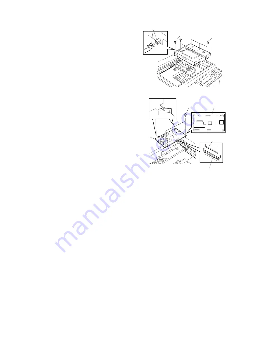
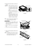
Fig. 7-8-18
Scanner
PWA
Flexible cable
Connector
051-1
Scanner PWA
Screw
5. Detach all the connectors from scanner PWA.
Note:
Route the flexible cable under scanner
PWA to avoid damage beforehand. When
attaching the flexible cable, securely lock
the connector locks on both sides of the
connector.
6. Remove 2 screws and remove scanner PWA.
Important:
1. After the replacement of the
scanner PWA, download firmware
for the scanner PWA. For details,
see chapter 5 of the Service
Handbook.
2. Download the MAIN PWA firmware,
if necessary, after confirming the
version of it.
3. After replacing the scanner PWA,
program 05-306, 304, and then
305, by referring to the Service
Handbook.
4. When the error message “F14”
appears after replacing the scanner
assembly, refer to the Service
Handbook and perform (08-389).
Note:
When removing scanner PWA, beware of
scanner drive shaft.
Note:
If the damp heater is installed, release one
hook and detach one connector.
(SAD/ASD/AUD/CND models)
Screw
Screw
Connector
Fig. 7-8-17
050-7
Summary of Contents for e-studio 160
Page 2: ... 2002 TOSHIBA TEC CORPORATION All rights reserved ...
Page 223: ...e STUDIO160 200 250 PCB BOARD 16 2 December 2002 TOSHIBA TEC 16 2 PWA F RLY 16 02 01 ...
Page 224: ...December 2002 TOSHIBA TEC 16 3 e STUDIO160 200 250 PC BOARD 16 3 PWA F PIF 16 03 01 ...
Page 226: ...December 2002 TOSHIBA TEC 16 5 e STUDIO160 200 250 PC BOARD 16 6 PWA F SLG 16 06 01 ...
Page 228: ...17 WIRE HARNESS CONNECTION DIAGRAMS 17 1 ...
Page 255: ...1 1 KANDA NISHIKI CHO CHIYODA KU TOKYO 101 8842 JAPAN ...


