December 2002 TOSHIBA TEC
7 - 29
e-STUDIO160/200/250 SCANNER
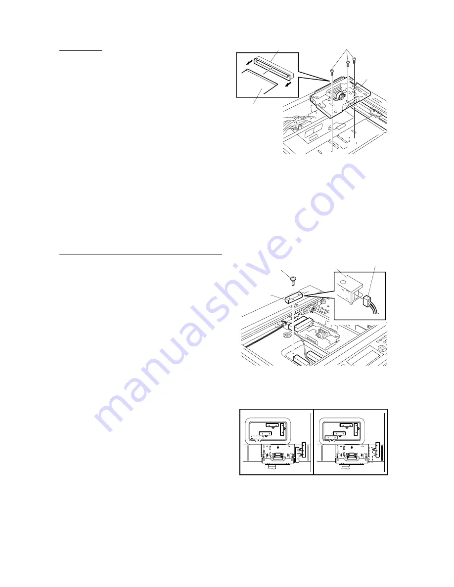
Fig. 7-8-33
CCD unit
Flat cable
Connector
Screw
065-10
[J] CCD unit
1. If an Original Cover (KA-1600PC), ADF
(MR-2012), or the RADF (MR-3011) is attached
to the copier, open it.
2. Remove original glass. (See Fig. 7-8-7)
3. Remove the blind plate.
(See Fig. 7-8-16 and 7-8-17)
4. Remove 3 screws, detach 2 connectors, and
remove CCD unit.
Notes:
1. When attaching the flexible cable, se-
curely lock the connector locks on both
sides of the connector.
2. For mounting the CCD unit and adjust-
ing the enlargement/reduction of images,
refer to the Service Handbook.
(See Chapter 1.8)
[K] Document size sensor (DP2000/2500 series)
1. If an Original Cover (KA-1600PC), ADF
(MR-2012), or the RADF (MR-3011) is attached
to the copier, open it.
2. Remove original glass. (See Fig. 7-8-7)
3. Remove the blind plate.
(See Fig. 7-8-16 and 7-8-17)
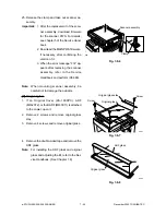
4. Remove 5 screws, detach 5 connectors, and
remove document size sensor.
Note:
When installing document size sensor, the
harness must not obstruct CCD.
Fig. 7-8-34
Fig. 7-8-35
065-5-5
Document
size sensor
065-5-4
Screw
Document
size sensor
Connector
NAD model
MJD/SAD/AUD/CND
models
Summary of Contents for e-studio 160
Page 2: ... 2002 TOSHIBA TEC CORPORATION All rights reserved ...
Page 223: ...e STUDIO160 200 250 PCB BOARD 16 2 December 2002 TOSHIBA TEC 16 2 PWA F RLY 16 02 01 ...
Page 224: ...December 2002 TOSHIBA TEC 16 3 e STUDIO160 200 250 PC BOARD 16 3 PWA F PIF 16 03 01 ...
Page 226: ...December 2002 TOSHIBA TEC 16 5 e STUDIO160 200 250 PC BOARD 16 6 PWA F SLG 16 06 01 ...
Page 228: ...17 WIRE HARNESS CONNECTION DIAGRAMS 17 1 ...
Page 255: ...1 1 KANDA NISHIKI CHO CHIYODA KU TOKYO 101 8842 JAPAN ...


