December 2002 TOSHIBA TEC
2 - 33
e-STUDIO160/200/250 OUTLINE OF THE MACHINE
High voltage
power supply
Screw
Screw
High voltage
power supply
026-2
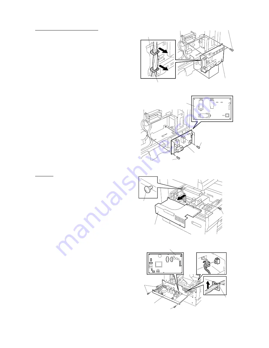
[D] High voltage power supply
1. If a STP (KK-1600) is attached to the copier,
disconnect the power cable.
2. Detach the manual pocket.
3. Detach rear cover. (See Fig. 2-6-1)
4. If a PCL kit (GA-1031) is attached to the copier,
detach it.
5. If a NIC kit (GF-1110) or I-FAX (GD-1070) is
attached to the copier, unplug the connectors
for CN14 and CN17.
6. Remove 2 screws, release 2 clamps, and
detach HVPS cover.
Clamp
Clamp
HVPS cover
Screw
026-1
Fig. 2-6-29
7. Detach all the connectors, remove 4 screws,
then remove high voltage power supply.
Fig. 2-6-30
Screw
LVPS cover
LVPS
Screw
Screw
LVPS
Clamp
027-1
027-2
Screw
[E] LVPS
1. If a Finisher (MJ-1011) is attached to the copier,
detach the finisher plate and junction block.
2. If a JSP (MJ-5001) or OCT (MJ-5002) is
attached to the copier, detach it.
3. Detach the toner cartridge.
4. Detach ozone cover. (See Fig. 2-6-9)
5. Detach paper tray cover. (See Fig. 2-6-10)
6. Loosen 5 screws.
7. Remove one screw and detach LVPS cover.
Fig. 2-6-31
8. Detach all the connectors and release one
clamps.
9. Remove 3 screws and remove LVPS.
Fig. 2-6-32
Summary of Contents for e-studio 160
Page 2: ... 2002 TOSHIBA TEC CORPORATION All rights reserved ...
Page 223: ...e STUDIO160 200 250 PCB BOARD 16 2 December 2002 TOSHIBA TEC 16 2 PWA F RLY 16 02 01 ...
Page 224: ...December 2002 TOSHIBA TEC 16 3 e STUDIO160 200 250 PC BOARD 16 3 PWA F PIF 16 03 01 ...
Page 226: ...December 2002 TOSHIBA TEC 16 5 e STUDIO160 200 250 PC BOARD 16 6 PWA F SLG 16 06 01 ...
Page 228: ...17 WIRE HARNESS CONNECTION DIAGRAMS 17 1 ...
Page 255: ...1 1 KANDA NISHIKI CHO CHIYODA KU TOKYO 101 8842 JAPAN ...


