MR-2015
OPTION MR-2015 (ADF)
15 – 7
6. ADJUSTMENTS
A. Auto white correction pixel adjustment
[Function]
The white correction start pixel position is automatically adjusted.
This adjustment is performed after the lens unit is replaced.
[Operation]
B. Magnification ratio adjustment
Note: • When performing this adjustment, check that the CCD unit is
properly installed.
• When performing this adjustment, check that the OC mode
adjustment in copying is completed.
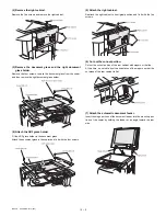
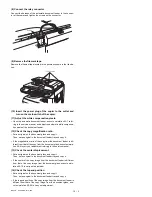
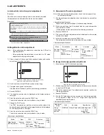
1) Place a scale on the document table as shown below, and make a
normal copy to make a test chart.
2) Set the test chart to the ADF and make a normal copy.
3) Compare the copy and the test chart.
If an adjustment is needed, perform the following procedures.
4) Execute SIM 48-5.
5) The current correction value is displayed on the display section in
two digits.
6) Enter the set value, and press the START key.
The entered correction value is stored and a copy is made.
7) Change the TEXT mode.
The TEXT lamp lights up, and the current correction value of the
back surface sub scanning direction magnification ratio is displayed
on the display section in two digits.
8) Enter the set value, and press the START key.
The entered correction value is stored and a copy is made.
<Adjustment specifications>
C. Document off center adjustment
Note: When performing this adjustment, check that the paper off-cen-
ter is properly adjusted.
1) Set the center position adjustment test chart (made by yourself) on
the ADF.
<Adjustment specifications>
Draw a line in the center of paper. (In the scanning direction)
2) Make a normal copy from the manual feed tray, and compare the
copy and the test chart.
If an adjustment is required, perform the following procedures.
3) Execute SIM 50-12.
4) The current off-center adjustment value is displayed on the display
section in two digits.
5) Enter the set value and press the START key.
The entered correction value is started and a copy is made.
<Adjustment specifications>
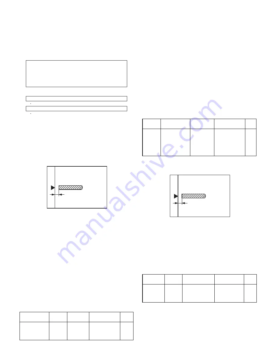
D. Image lead edge position adjustment
1) Set a scale on the OC table as shown below.
2) Make a copy, and use the copied paper as the document and make
a copy from ADF again.
3) Check the copied paper. If an adjustment is required, perform the
following procedures.
4) Execute SIM 50-6.
5) Set the ADF lead edge position set value so that the image similar
to the adjusted image at the OC image lead edge position
described previously is printed.
<Adjustment specifications>
Mode
Spec
SIM
Set value
Set
range
Magnification
ratio adjustment
Normal:
m
1.0%
SIM 48-5
AE: Surface
TEXT: Back
Add 1:
0.1% increase
Reduce 1:
0.1% decrease
1 ~ 99
During execution,"EXEC" is highlighted
Open the ADF unit and press the [OK] key.
7-segment indicates the order number of the pixel of the white sheet for ADF exposure
correction in the ADF position.
It will display on 7-segment, if values are 93-299, and data are written into the EEPROM.
It will display on 7-segment, it values are 0-92 or 230-999, and data are not written into
the EEPROM.
It will display "--" on 7-segment, it values is 1000 or larger, and data are not written into
the EEPROM..
The ADF white correction start pixel = Displayed pixel position - 34
If the simulation is executed with the ADF unit closed, an error is resulted.
[CA] key: Cancels the test command.
[Interruption] key: Shifts to the sub code entry menu.
Interruption is inhibited during execution.
Note: Since the printed paper is used as the test chart,
place the scale in parallel to both sides.
Mode
Specification
SIM
Set value
Set
range
Document
off-center
Simplex:
Center
m
3.0mm
Duplex:
Center
m
3.5mm
AE: Surface
TEXT: Back
Add 1:
0.1mm shifted to
R side.
Reduce 1:
0.1mm shifted to L
side.
1 ~ 99
Adjustment
mode
SIM
Set value
Specification
Set
range
Image
lead edge
position
SIM 50-6 1step: 0.1mm shift Lead edge void:
1 ~ 4mm
Image loss:
3mm or less
1 ~ 99
Note: Since the printed paper is used as the test chart,
place the scale in parallel to both sides.

