background image

SERVICE MANUAL

MULTIFUNCTIONAL DIGITAL SYSTEMS

e-STUDIO202S

Model: DP-2021
Publish Date: July 2008
File No. SME080001A0
R080621G0400-TTEC
Ver01_2008-09

Summary of Contents for e-Studio 202S

Page 1: ...SERVICE MANUAL MULTIFUNCTIONAL DIGITAL SYSTEMS e STUDIO202S Model DP 2021 Publish Date July 2008 File No SME080001A0 R080621G0400 TTEC Ver01_2008 09 ...

Page 2: ...of Adobe Systems Incorporated in the United States and other countries IBM PC AT and PowerPC are trademarks of International Business Machines Corporation All other trademarks and copyrights are the property of their respective owners 2008 TOSHIBA TEC CORPORATION All rights reserved Under the copyright laws this manual cannot be reproduced in any form without prior written permission of TOSHIBA TE...

Page 3: ...uring service Be sure not to touch high temperature sections such as the exposure lamp the fuser unit and their periphery Be sure not to touch high voltage sections such as the chargers and the high voltage trans former Especially the board of these components should not be touched since the electric charge may remain in the capacitors etc on them even after the power is turned OFF Be sure not to ...

Page 4: ...osition of Consumable Parts Packing Materials Regarding the recovery and disposal of the machine supplies consumable parts packing mate rials follow the relevant local regulations or rules 6 When parts are disassembled reassembly is basically the reverse of disassembly unless otherwise noted in this manual or other related documents Be careful not to reassemble small parts such as screws washers p...

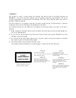
Page 5: ...ng wedges or other items into the switch slot LASER WAVE LENGTH 770 795nm Pulse times 0 481m sec 20 787 rpm Out put power 0 17mW 0 01mW CAUTION INVISIBLE LASER RADIATION WHEN OPEN AND INTERLOCKS DEFEATED AVOID EXPOSURE TO BEAM VORSICHT UNSICHTBARE LASERSTRAHLUNG WENN ABDECKUNG GEÖFFNET UND SICHERHEITSVERRIEGELUNG ÜBERBRÜCKT NICHT DEM STRAHL AUSSETZEN VARO AVATTAESSA JA SUOJALUKITUS OHITETTAESSA OL...

Page 6: ...able only to the 220V model 230V model and 240V model VAROITUS LAITTEEN KÄYTTÄMINEN MUULLA KUIN TÄSSÄ KÄYTTÖOHJEESSA MAINITULLA TAVALLA SAATTAA ALTISTAA KÄYTTÄJÄN TURVALLISUUSLUOKAN 1 YLITTÄVÄLLE NÄKYMÄTTÖMÄLLE LASERSÄTEILYLLE VARNING OM APPARATEN ANVÄNDS PÅ ANNAT SÄTT ÄN I DENNA BRUKSANVISNING SPECIFICERATS KAN ANVÄNDAREN UTSÄTTAS FÖR OSYNLIG LASERSTRÅLNING SOM ÖVERSKRIDER GRÄNSEN FÖR LASERKLASS ...

Page 7: ...on 8 4 A List 8 4 B Disassembly procedure 8 4 C Assembly procedure 8 5 3 Optical section 8 5 A List 8 5 B Disassembly procedure 8 5 C Assembly procedure 8 6 4 Fusing section 8 7 A List 8 7 B Disassembly procedure 8 7 C Assembly procedure 8 10 5 Tray paper feed transport section 8 10 A List 8 10 B Disassembly procedure 8 10 C Assembly procedure 8 15 6 Manual paper feed section 8 15 A List 8 15 B Di...

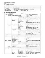
Page 8: ...function GDI printer GDI printer function with USB PCL printer PCL printer function with USB E SORT Electronic sort function Duplex Auto duplex copy print function Shifter Job separator function USB Interface port USB RJ45 Interface port Network FAX FAX function Descriptions of table Standard provision No function or no option available Opt Option Item CPM A4 PPM A4 SB MB 2 Tray ADF R ADF Color Sc...

Page 9: ...recycled paper Remark User adjustment of paper guide available Multi bypass paper feed section Paper size 8 1 2 x 14 8 1 2 x 11 8 1 2 x 5 1 2 3 1 2 x 5 1 2 Landscape Paper weight 15 34 5 lbs Paper feed capacity 50 sheets Kinds Standard paper specified paper recycled paper OHP Label Envelop Single copy Remark User adjustment of paper guide available Paper exit section Exit way Face down Capacity of...

Page 10: ... 86 100 141 200 Inch system 50 64 78 100 129 200 Zooming magnification ratios 25 400 376 steps in 1 increments 50 200 when using ADF 151 steps in 1 increments Manual steps manual photo 5 steps Copy speed First copy time 1 Approximately 8 0 seconds When user program 24 is set to OFF 10 7 seconds When user program 24 is set to ON paper A4 8 1 2 x 11 exposure mode AUTO copy ratio 100 AB system A4 Lan...

Page 11: ...ource 3 CCDs RGB sensor scanning by lighting white lamp 2 pcs of CCFL Resolution Optical 600 x 1200dpi Setting range 50 9600dpi Preview resolution is fixed at 75dpi Originals Sheet type Book type Output data R G B 1 or 8 bits pixel A D 16 bits 12 bits actual Scan range OC ADF 216mm H x 356mm V 8 5 H x 14 0 V Original position Left Center ADF position Right Center Scan speed OC ADF Max 2 88ms line ...

Page 12: ...r cartridge Black Toner Toner Net Weight 243g 10 80K 8K x 10Pcs PS ZT2021 A4 6 document One carton of the PS ZT2021 includes 10 toner cartridges Polyethylene bag 10 2 Developer Developer Developer Net Weight 170g 10 250K 25K x 10Pcs D 2021 One carton of the D 2021 includes 10 developers 3 Drum kit Drum 1 25K OD 1200 One carton of the collective package includes 10 units of the OD 1200 Drum fixing ...

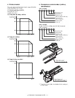
Page 13: ...cartridge shows the date of production SOCC production 1 The production control label is not attached to the cartridge of a China product Humidity RH 85 60 20 10 C 30 C 35 C Humidity RH 90 60 15 25 C 30 C 40 C Humidity RH 90 20 5 C 45 C Production month Production day Destination code Dealer distributor OEM etc Production place SOCC Fixed to B End digit of year Version No Production month Producti...

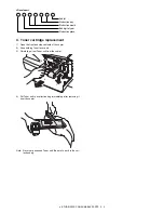
Page 14: ...er 2 Keep holding Toner lever and 3 Carefully pull out Toner unit from the copier 4 Put Toner unit in a collection bag immediately after removing it from the copier Note Never carry exposed Toner unit Be sure to put it in the col lection bag Sub lot Production day Production month End digit of year Production place 1 3 2 ...

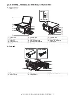
Page 15: ...over 5 Paper tray 6 Multi bypass tray 7 Side cover 8 Side cover open button 9 Bypass tray paper guides 10 Paper output tray 11 Paper output tray extension 12 Power switch 13 Handle 14 Power cord 1 Front cover 2 Side cover 3 Fusing unit release lever 4 Transfer charger 5 Charger cleaner Interface USB connector 3 4 5 1 2 7 9 8 6 10 11 12 14 13 3 4 5 2 1 Toner cartridge Drum cartridge ...

Page 16: ...ing without changing the zoom ratio Use to check the number of originals that must be returned to the document feeder tray if an original misfeed occurs while using the ADF 8 Display Displays the specified copy quantity zoom copy ratio user program code and error code 9 SCAN key and indicator 2 3 10 ONLINE key and indicator Lights up when the unit is used as a printer and scanner 2 11 Start key an...

Page 17: ...n numbers are initially as follows 4 Press the start key Scanning will start and the scanned data will be transferred to the application On Indicates the unit is in a power save mode Blinking Indicates that the unit is initializing when the side cover is opened and closed or the power turned off and on On The SCAN key has been pressed and the unit is in scanner mode Blinking A scan job is being ex...

Page 18: ...es the copier 2 Scanner motor MRMT Drives the optical mirror base scanner unit 3 Toner motor TM Supplies toner 4 Cooling fan motor VFM Cools the optical fusing section 5 Resist roller solenoid RRS Resist roller rotation control solenoid 6 Paper feed solenoid CPFS1 Cassette Paper feed solenoid 1 7 Multi paper feed solenoid MPFS Multi manual pages feed solenoid ...

Page 19: ... POD sensor POD Transmission sensor Paper exit detection H at paper pass 3 PPD2 sensor PPD2 Transmission sensor Paper transport detection 2 L at paper pass 4 Cassette detection switch CED1 Micro switch Cassette installation detection H at cassette insertion 5 PPD1 sensor PPD1 Transmission sensor Paper transport detection 1 L at paper pass 6 Door switch DSW Micro switch Door open close detection sa...

Page 20: ...r PWB Exposure lamp CCFL control 2 Main PWB MCU Copier control 3 Operation PWB Operation input display 4 High voltage PWB High voltage control 5 CCD sensor PWB For image scanning 6 LSU motor PWB For polygon motor drive 7 TCS PWB For toner sensor control 8 LSU PWB For laser control 9 Power PWB AC power input DC voltage control ...

Page 21: ...oller for paper exit 5 Main charger Provides negative charges evenly to the drum surface 6 Heat roller Fuses toner on the paper Teflon roller 7 Pressure roller Fuses toner on the paper Silicon rubber roller 8 Drum Forms images 9 Transfer unit Transfers images onto the drum 10 Pickup roller Picks up the manual feed paper In multi feed only 11 Manual paper feed tray Tray for manual feed paper 12 Man...

Page 22: ... current requirements Also make certain the outlet is properly grounded Be sure to allow the required space around the machine for servic ing and proper ventilation 2 Cautions on handling Be careful in handling the copier as follows to maintain the perfor mance of this copier Do not drop the copier subject it to shock or strike it against any object Do not expose the drum cartridge to direct sunli...

Page 23: ...ng switch hold up the catch in illus tration A and turn the center knob counter clockwise 90 degrees until you hear a click 6 Developer unit installation 1 Open the multi bypass tray and then open the side cover 2 Remove the CAUTION tape from the front cover and remove the two protective pins from the fusing unit by pulling the strings upward one at a time 3 Push gently on both sides of the front ...

Page 24: ...re to insert carefully 14 Confirm that Developer unit is completely inserted to the bot tom of the machine fix Developer unit and the machine with a screw 15 Completion of Developer unit installation 7 Toner cartridge installation 1 To prevent against uneven distribution of toner hold Toner unit with both hands and shake it several times horizontally 2 Hold the section of Toner unit shown in the f...

Page 25: ...canner driver The scanner driver allows you to use the scanning function of the machine with TWAIN compliant and WIA compliant applications Desktop Document Manager Desktop Document Manager is an integrated software environ ment that makes it easy to manage documents and image files and launch applications Button Manager Button Manager allows you to use the scanner menus on the machine to scan a d...

Page 26: ...er and side cover in that order To open and close the side cover and front cover and to remove the toner cartridge 3 Raise the handle of the paper tray and pull the paper tray out until it stops 4 Push the center of the pressure plate down until it locks in place and lock the plate using the pressure plate lock which has been stored in the front of the paper tray 5 Push the paper tray back into th...

Page 27: ...R part the yellow line in the diagram below so that the hole of the metal plate is covered as much as possible Align the edge of the mylar to the R part the yellow line in the diagram below so that the hole of the metal plate is covered as much as possible Attach along the edge of the projection the yellow line in the diagram below 5 Attach the Optical right hole mylar B at the 2 positions shown i...

Page 28: ... surface cushion on the top and the rear side at the rear side of the main unit Align the cushion with the side of the raised part the yellow line in the diagram below Bend the part which is sticking out to the rear side of the scan ner and attach to the surface Press the cushion at the steps shown in the diagram so that there will be no gap Press the cushion to make sure all the holes are covered...

Page 29: ...ion covering the bottom part of the Scanner motor lower mylar Note The hole under the motor unit should be covered Attach the cushion to cover the gap between the mylar and the metal plate the yellow mark Press the cushion with a sharp pointed stick or something to fill the gap between the mylar and the metal plate 11 Attach the motor connector and the snap band to the original position 12 Attach ...

Page 30: ... the machine Note Please make sure the double sided tape is not exposed where the cushion is sticking out from the edge of the fan housing Attach the cushion leaving 3 7mm from the edge so that the gap between the Fan housing cushion and the filter of the rear cabinet is filled for sure 14 Attach the parts removed in the items 1 2 and 3 A View from the arrow A Back side Attach the cushion leaving ...

Page 31: ...eam MG roller Cleaning blade Drum Transfer unit Resist roller Exposure Main high voltage unit Saw tooth Charge Drum Cleaning Cleaning blade Waste toner box Paper release Fusing Separation Heat roller Heater lamp Transfer Transfer charger Transfer high voltage unit Developing Toner Developer Print process Paper transport route Semiconductor laser Manual feed PS roller Focus correction lens Electrod...

Page 32: ...Cleaning Residual toner on the drum surface is removed and col lected by the cleaning blade Step 6 Optical discharge Residual charge on the drum surface is removed by semiconductor laser beam 3 Actual print process Step 1 DC charge A uniform negative charge is applied over the OPC drum surface by the main charging unit Stable potential is maintained by means of the Scorotron charger Positive charg...

Page 33: ...Step 4 Transfer The visible image on the drum surface is transferred onto the print paper by applying a positive charge from the transfer corona to the backside of the print paper Step 5 Separation Since the print paper is charged positively by the transfer corona it is discharged by the separation corona The separation corona is applied negative charge Step 6 Cleaning Toner remaining on the drum ...

Page 34: ...ed the carrier is attracted to the drum because of the strong electrostatic force of the drum To avoid this the process is controlled by adjusting the drum potential and the grid potential of the Scorotron charger Basic function Voltage added to the screen grid can be selected high and low To make it easily understood the figure below shows voltage transi tion at the developer unit Start 1 Because...

Page 35: ...gnals are converted into photo signals 6 The laser beams are radiated through the polygon mirror and various lenses to the OPC drum Printing 7 Electrostatic latent images are formed on the OPC drum according to the laser beams and the latent images are devel oped to be visible images toner images 8 Meanwhile the paper is fed to the image transfer section in synchronization with the image lead edge...

Page 36: ...olor scanning When PC scanning The resolution is 600dpi When copying only the green component is used to print with the printer The color component for printing can be switched to red or blue by the service simulation Spectrum characteristics of the lamp Spectrum characteristics of the color CCD Optical unit C Drive system The drive system is composed of the scanner motor the pulley gear the idle ...

Page 37: ...asurement of the laser writing start point Makes the laser scanning speeds at both ends of the drum same as each other B Laser beam path C Composition Effective scanning width 216mm max Resolution 600dpi Beam diameter 75um in the main scanning direction 80um in the sub scanning direction Image surface power 0 18 0 01mW Laser wavelength 770 795nm Polygon motor section Brushless motor 20 787rpm No o...

Page 38: ...or This model is provided with a fusing resistor in the fusing section to improve transfer efficiency Since the upper heat roller is conductive when using copy paper that contains moisture and the distance between the transfer unit and the fusing unit is short the transfer current may find a path to ground via the copy paper the upper heat roller and the discharg ing brush 5 Paper feed section and...

Page 39: ...n contact with a notch on the clutch sleeve stopping rotation of the pick up roller 5 At this time the paper is fed passed the paper entry detection switch PPD1 and detected by it After about 0 15 sec from detection of paper by PPD1 the tray paper feed solenoid PFS turns on so that the clutch sleeve projection comes into contact with the paper feed latch to stop the pick up roller Then the pick up...

Page 40: ...s pressed to the surface of the paper to start paper feeding 3 When pawl C of the manual paper feed clutch sleeve is engaged with the manual feed latch the manual feed stopper falls and the manual take up roller rises At that time the man ual paper feed roller is rotating 4 The lead edge of the transported paper is pressed on the resist roller by the transport roller Then the paper is stopped temp...

Page 41: ...on a PPD1 jam PPD1 does not turn off within 4 sec after turning on the resist roller b PPD2 jam PPD2 is off immediately after turning on the resist roller PPD2 does not turn off within 1 2 sec after turning off the resist roller c POD jam POD does not turn on within 2 9 sec after turning on the resist roller POD does not turn off within 1 5 sec 2 7 sec after turning off PPD2 ...

Page 42: ...no damage execute the procedure of item 12 4 Remove the main charger Cleaning the screen grid and the sawteeth 5 Remove the cleaning blade Note Dispose the cleaning blade which was removed Before disassembly be sure to disconnect the power cord for safety 1 Do not disconnect or connect the connector and the harness during the machine is powered Especially be careful not to disconnect or connect th...

Page 43: ...he cleaning blade Do not put the mocket on the sub blade Do not press the sub blade with the mocket 10 Attach the main charger Securely set the MC holder on the projection of the process frame Securely insert two projections of the MC holder into the groove in the process frame When attaching the MC holder ass y be careful not to make contact with the cleaning blade 11 Attach the drum fixing plate...

Page 44: ...n the side cover 2 Push up the lock pawls 2 positions of the side cover and remove the transfer charger D Assembly procedure For assembly reverse the disassembly procedure E Charger wire cleaning 1 Remove the charger cleaner from the manual paper feed unit 1 2 2 1 1 Transfer charger Lock pawl rear Lock pawl front 1 ...

Page 45: ...s 1 and 2 At that time be careful of the following items The rest of the charger wire must be within 1 5mm Refer to Fig 1 The spring hook section charger wire winding section must be in the range of the projection section Be careful not to twist the charger wire 2 Operation panel section A List B Disassembly procedure 1 Open the side door and Open the front cover 2 Remove the screws 4 pcs the harn...

Page 46: ...crews and remove the rear cabinet and the rear cabinet cover 2 Remove two screws and remove the earth wire 3 Disconnect the connector 4 Remove the original cover 5 Remove five screws Remove the operation unit and discon nect the connector 6 Remove the right cabinet 7 Remove the left cabinet 8 Remove the screw and remove the rear cover 9 Remove the table glass NO Part name Ref 1 Copy lamp unit 2 Co...

Page 47: ...to the CCD PWB connector of the carriage unit 3 Move the core which was passed through the CCD MCU har ness near the CCD PWB connector as shown in the figure below and fix it with a filament tape 19mm wide 40mm long For the attachment reference refer to the figure below Clean and remove oil from the attachment section 4 Attach the CCD MCU harness to the duplex tape on the back of the carriage unit...

Page 48: ...n guide Note When installing the resistor check to confirm that the discharge brush section A is in contact with the upper heat roller Also check to confirm that the fusing lower earth spring B does not extend over the fusing bearing C after tightening the screw Pressure roller section disassembly 5 Remove the three screws remove the fusing cover lower on the right side and open the heat roller se...

Page 49: ...g unit is opened without sliding the fusing lower earth spring the fusing lower earth spring is deformed If the fusing lower earth spring is once deformed the earth function may not work properly Replace the deformed spring with a new one 9 Remove the spring and remove the upper separation pawls 3 pcs 10 Remove the E ring and remove the reverse gate 11 Remove the spring and remove the lower separa...

Page 50: ...risk Grease JFE552 Heat roller disassembly Continued from procedure 4 5 Remove screws remove the fusing cover and open the heat roller section 6 Remove the C ring and the fusing bearing and remove the heat roller 7 Remove the parts from the heat roller Note Apply grease to the sections specified with 1 Grease JFE552 1 1 1 2 2 1 3 3 Pressure roller 1 2 2 3 3 1 2 3 Heat roller 3 2 1 1 1 2 Apply grea...

Page 51: ... transport section A List B Disassembly procedure 1 Remove two screws and remove the hinge guide R 2 Disconnect the connector 2 positions 3 Remove five screws and remove the scanner unit 4 Remove the fan duct 5 Remove each connector and four screws and remove the MCU PWB Temperature Current model 210 C e STUDIO202S 230 C No Part name Ref 1 PPD1 sensor PWB 2 LSU unit 3 Intermediate frame unit 4 Pap...

Page 52: ...sulation mylar and remove the paper transport detection sensor PPD2 7 Remove two screws and remove the toner motor 8 Remove two springs and open the intermediate frame unit 9 Remove the pulleys on the both sides and remove the paper exit roller 2 1 1 2 1 2 4 2 1 3 ...

Page 53: ...EMBLY AND ASSEMBLY 8 12 10 Pull out the paper exit roller knob and remove the belt 11 Release the belt pulley lock and remove the belt pulley bear ing 12 Remove the paper exit roller 13 Remove the harness guide 1 2 2 3 1 ...

Page 54: ...r feed solenoid 16 Remove four screws and remove the paper guide unit 17 Remove four screws and remove the LSU unit Note for assembling the LSU When installing the LSU turn the LSU clockwise and fix with screws in order to provide an attachment backlash in the proper direction Observe the following sequence of fixing screws 1 3 2 1 CAUTION Attach the gears securely 3 3 1 1 2 2 4 4 2 1 1 1 1 1 1 2 ...

Page 55: ... lift the intermedi ate frame unit to remove 21 Remove the screw and the E ring and remove the PS semi circular earth plate and the PS roller unit 22 Remove the E ring and remove the spring clutch from the PS roller unit 23 Remove three screws and remove the TC front paper guide 5 1 2 3 4 2 2 3 4 1 5 4 4 1 2 3 PS roller unit PS semi circuler earth plate 5 4 4 1 2 3 PS semi circular earth plate Use...

Page 56: ...and remove the clutch unit C Assembly procedure For assembly reverse the disassembly procedure 6 Manual paper feed section A List B Disassembly procedure Multi unit 1 Remove the screw and remove the multi upper cover 1 2 4 5 1 2 3 4 Back Front Clutch unit Paper feed roller No Part name Ref 1 Manual transport roller 2 Cassette detection switch 3 PPD1 sensor PWB 4 Side door detection unit 2 1 ...

Page 57: ...n unit 3 Remove three screws and remove the multi paper feed upper frame 4 Remove two screws and remove the multi feed bracket unit from the multi paper feed upper frame 5 Remove three E rings and remove the manual paper feed roller B9 1 2 Back Wire treatment 1 2 1 2 2 1 1 2 1 1 1 3 L O C K T O K ...

Page 58: ...hment 1 Attach the pressure plate holder so that the resin section is not covered with the seal M1 N 7 Rear frame section A List B Disassembly procedure 1 Remove four screws and remove the rear cabinet and the rear cabinet cover 2 1 1 2 3 Multi paper feed solenoid No Part name Ref 1 Scanner motor 2 Main motor 3 Exhaust fan motor 4 NIC PWB 5 Main PWB Pressure plate holder Seal M1 N Attachment refer...

Page 59: ... the MCU PWB C Assembly procedure For assembly reverse the disassembly procedure 8 Power section A List B Disassembly procedure 1 Disconnect each connector 2 Remove the screw and remove the earth line 3 Remove two screws and remove the power PWB unit Caution Be careful not to touch the sharp edge on the circumfer ence of the metal frame for the power supply C Assembly procedure For assembly revers...

Page 60: ... not within the specified range perform the follow ing procedures 7 Execute SIM 48 1 to select the main scanning direction copy magnification ratio adjustment mode To select the adjustment mode use the copy mode select key If the magnification ratio is not in the specified range 100 1 0 manually adjust as follows 8 Enter the new set value of main scanning direction copy mag nification ratio with t...

Page 61: ... the copy mode select key The relationship between the adjustment modes and the lighting lamps are as shown in the table below Machine with the multi manual paper feed unit Supported for the installing model and skipped for non install ing mode Copy image dimensions X 100 Original dimension 100 110 120 130 150 140 mm 1 2mm JAPAN HARDDENCD STAINLESS Shizuoka 100 110 120 130 150 140 mm 1 2mm JAPAN H...

Page 62: ...in the figure below and cover it with B4 or 8 1 2 x 14 paper 2 Execute SIM 50 01 to select the image rear edge void amount adjustment mode The set adjustment value is displayed on the copy quantity dis play 3 Make a copy and measure the void amount of image rear edge 4 If the measurement value is out of the specified range change the set value and repeat the adjustment procedure The default value ...

Page 63: ... of the copy density adjustment Clean the optical section Clean or replace the charger wire Check that the voltage at the high voltage section and the devel oping bias voltage are in the specified range C Necessary tool for copy density adjustment KODAK GRAY SCALE Test chart B4 14 x 8 1 2 white paper The user program AE setting should be 3 D Features of copy density adjustment For the copy density...

Page 64: ...ume VRG1 so that the output voltage is 580 12V Caution Be careful not to touch the sharp edge on the circumfer ence of the metal frame for the power supply B DV bias check Procedures 1 Set the digital multi meter range to DC500V 2 Set the positive side of the test rod to the connector CN 10 1 DV BIAS and set the negative side to the frame ground power frame 3 Execute SIM 8 1 to output the developi...

Page 65: ...nt of white balance When SIM 63 02 is executed the current correction value is dis played in 3 digits of 12bit hexadecimal number Place the gray gradation chart KODAK GRAY SCALE used as the correction document so that the density 10 black side comes on the left side and that the chart is upside down at the center of the plate left center When START key is pressed the mirror base unit scans the cha...

Page 66: ...OPY key The entered value is registered Is it the Perform the operation according to the simulation number performed Press the clear key All displays on the operation panel go off and the machine enters the ready state for entering the main code Press the clear key End Is the main code the same Is the sub code displayed Press the clear key The COPY QUANTITY display blinks to indicate the previousl...

Page 67: ...x setup 06 Destination setup 26 Various setup 07 Machine conditions check 20 Rear edge void setup 30 CE mark support control ON OFF 37 Cancel of stop at developer life over 39 Memory capacity check 40 Polygon motor OFF time setup Time required for turning OFF after completion of printing 42 Transfer ON timing control setup 43 Side void setup 54 γ life correction setup 62 Energy save mode copy lamp...

Page 68: ...g lamps 03 ADF motor ON ADF model only Operation Procedure When the START key is pressed the ADF motor rotates for 10 sec at the speed corresponding to the currently set magnification ratio 05 01 Operation panel display check When the START key is pressed all LEDs including 7 segment LEDs on the operation panel are lighted LED check mode When 1Up key is pressed the LEDs on the operation panel are ...

Page 69: ...ssed the operation is terminated The 7 seg display indicates the sub code Warming up operation is continued After completion of warming up counting is terminated This is similar to SIM 07 01 without the aging function 08 01 Developing bias Operation Procedure When the START key is pressed the developing bias is outputted for 30 sec 02 Main charger Grid high Operation Procedure When the START key i...

Page 70: ... the same as the total count value display 18 Printer counter display The display method is the same as the total count value display 19 Scanner mode counter display Scanner model only The display method is the same as the total count value display 21 Scanner counter display The display method is the same as the total count value display 22 ADF JAM counter display ADF model only The display method...

Page 71: ...urrently set duplex code number is displayed 2 Enter the code number corresponding to the duplex and press the START key and the setup will be changed 06 Destination setup When this simulation is executed the current setup of the destination code number is displayed Enter the code number corresponding to the destination and press the START key to enable the setup 07 Machine conditions check When t...

Page 72: ... setup Operation Procedure 1 When this simulation is executed the currently set code number of the side void amount is displayed 2 Enter the code number and press the START key The setting is changed 54 γ life correction setup Operation Procedure 1 When this simulation is executed the currently set code number is displayed 2 Enter the code number and press the START key The setting is changed Main...

Page 73: ...oat detection level adjustment if the number of pixels between the markers when processing float detection is less than the number of pixels set with this simulation it is judged as the float error In addition if the set value of this simulation is 0 no float error occurs When this simulation is executed the current set value is displayed Enter the adjustment value with UP UP key and press START k...

Page 74: ...EEPROM The display returns to the sub code input standby mode 14 Fusing start temperature setting The fusing temperature when starting printing first second sheet is set When this simulation is executed the currently set code number is displayed When the code number is entered with UP UP key and the START key is pressed setting is changed over The exposure select key is used to select the mode The...

Page 75: ...e brighter Press the CLEAR key to save the setup and exit from the simulation mode The exposure select key is used to select the mode The set value of the selected mode is displayed on the 7seg adjustment range 1 99 02 Copy density adjustment 600dpi Used to set the copy density in each mode Operation Procedure When this simulation is executed the machine performs warm up and shading and the curren...

Page 76: ...ed the mode is returned to the gamma table setup mode PHOTO image process setting When the exposure select key is pressed in the AE operation mode setting the mode is changed to the PHOTO image process setting and the currently set code number of the PHOTO image process setting is displayed Default 0 When the code number corresponding to the desired Photo image process setting is entered and the e...

Page 77: ... select key For UP keys only 1UP key is valid 10UP key is invalid Remark When SIM 26 06 is changed or SIM 46 19 automatic exposure mode is changed this setting is also changed to the default value 31 Image sharpness adjustment Used to adjust the clear shading off of an image in each mode Operating procedure When this simulation is executed warm up and shading operations are performed and the curre...

Page 78: ...selected by pressing the exposure select key When there is no document in the ADF copy is inhibited 49 01 Flash ROM program writing mode Operating procedure When this simulation is executed d is displayed on the display and the machine enters the Flash ROM program writing mode Use the writing tool to write the program from PC During writing the display indicates as shown below After completion of ...

Page 79: ...n opposite to the scan start position Each mode can be selected by pressing the exposure select key When there is no document in the ADF copy is inhibited 10 Center offset adjustment Used to adjust the copy image position on the copy paper and the center offset position when scanning a document Operating procedure When this simulation is executed the current setup value is displayed Enter the adju...

Page 80: ...ver edge position is determined from the difference in the CCD output levels of the ADF glass cover edge and the OC side document glass If the adjustment is completed normally the adjusted value is displayed on the 7seg LCD If it is terminated abnormally the following lamp is turned ON JAM lamp When the operation is canceled by pressing C key during execution the mirror is returned and is displaye...

Page 81: ...When the difference between the minimum value and the maximum value of the light quantity levels sampled for 3 2 sec in 100msec cycle in the light quantity stabilization process on white balance is smaller than the set value of this simulation it is judged that the light quantity is stabilized Note The magnification ratio of the AFE gain setting is automatically reflected on the stabilization band...

Page 82: ...e LSU operations Check that the polygon motor rotates normally Check that the laser emitting diode generates laser beams Replace the LSU unit Replace the MCU PWB E7 10 Content Shading trouble Black correction Detail The CCD black scan level is abnormal when the shading Cause Improper connection of the CCD unit flat cable CCD unit abnormality MCU PWB abnormality Check and remedy Check connection of...

Page 83: ...n the target temperature 165 C is not reached in 55 sec after starting warming up 2 When the temperature below 100 C is detected for 300ms under the ready print state Starting warming up means not only that in power supply but also reset that in reset from shut off and in side door close The timing of generating H4 is not limited to that in power supply Cause Thermistor abnormality Heater lamp abn...

Page 84: ...r 1 sec after starting detection 2 When the lock sensor in the exhaust fan detects the HIGH level unstable after detection the lock state stable state Cause Exhaust fan motor connector connection trouble Exhaust fan motor trouble MCU PWB trouble Check and remedy Exhaust fan motor connector connection check Exhaust fan motor replacement Replace the MCU PWB Main code Sub code Details of trouble L6 1...

Page 85: ...e DV side seal F R Process peripheral Drum Toner Life 8K Remaining quantity NEAR EMPTY About 12 5 EMPTY LED ON Flash Machine Operation allowed Stop Developer Life 25K LED ON at 25K of the developer count Machine Selection is available between Not Stop and Stop by Service Simulation SIM 26 37 Setup If Stop is selected the LED will flash and stop at 25K Default Not Stop Clear SIM 24 06 Maintenance L...

Page 86: ...xposure mode selector key The PHOTO indicator will stop blinking and light up steadily The light and dark indicator marked 3 will light up The toner save mode is now active Note To return to the standard mode repeat the procedure but use the dark key to select exposure level 5 in step 3 3 User programs The user programs allow the parameters of certain functions to be set changed or canceled as des...

Page 87: ...r key The unit will return to step 2 6 Press the light key to return to the normal copy mode 25 Copy effective paper width setting function Bypass tray 1 Large A4 width LETTER 2 Small B5R width INVOICE 26 Copy effective paper width setting function Tray 1 Large A4 width LETTER 2 Small B5R width INVOICE 28 Selection of copy start state Polygon rotation on off 1 ON 2 OFF 29 Fusing temperature settin...

Page 88: ...ock detect 8Kbyte 24V 12V 2nd Cassette MainMotor Toner Motor Mirror Motor Polygon Mechanical load Motor CPFS2 Sensor SW PAPD PPD3 PD2 CED2 AC Code LSU KRONOS ASIC 296pin CPU H8S 2321 19 6608MHz EEPROM SDRAM 16Mbyte or 8Mbyte Reset IC SRAM Driver Flash ROM AFE HT82V24 C D S A G C M P X AD 16bits CCD Driver CCFL x 2 Lamp Inverter for CCFL HOME POSITION SENSOR CCD ILX558X CPU CLK 19 6608MHz System Re...

Page 89: ...24V MMD PGND AFE_DB4 AFE_DB3 CPFS1 1 INT24V PGND MMD 1 2 3 HLN HLL HLL 3 GRID MCFB TC MC BIAS TC 24V 1 SHOLD SYNC INT5V D GND LDEN VIDEO 8 1 2 1 2 D GND 2 3 4 5 1 12VIN 24V FW P GND 24V PR HLOUT P GND EN5V 3 3VIN 5V POFF D GND P GND D GND 3 3VIN PR HLOUT P GND P GND 12VIN 24V FW 24V EN5V 3 3VIN 5V POFF D GND P GND D GND 3 3VIN BC BIAS TC GRIDL MC BIAS F GND MC GRIDL INT5V INT24V INT5V INT24V BIAS ...

Page 90: ... SPID 7 DGND 8 SPMT_1 5 SPMT_3 6 SPMT_0 3 SPMT_2 4 24VSPFMT 1 24VSPFMT 2 MCU PWB SPID SPMT ADF UNIT SPPD CN18 B14B PHDSS B 2 CPFS2 2 13 24V 2 1 24V 1 14 CPFS2 1 11 5V 4 8 PPD3 7 11 13 3 7 D GND 8 PD2 9 6 4 2 1 5 9 D GND CED2 D GND FG 14 10 3 9 10 14 6 8 11 12 13 1 2 4 7 3 5 6 9 D GND CPFS2 24V 5V PPD3 D GND PD2 D GND CED2 5 10 PD2 1 D GND 2 9 D GND 1 5V 3 PPD3 2 CED2 1 D GND 2 MCU PWB CPFS2 PPD3 P...

Page 91: ... CS pickup solenoid Paper transport section CED1 Machine cassette detection Paper transport section LEDPPD1 PPD sensor power Paper transport section PPD1 PPD sensor Paper transport detection Paper transport section MPFS Multi bypass solenoid Optical section KEYIN1 Key scan input Key detection control Operation section SELIN3 Select signal 3 HC151 select signal Operation section STROBE LED driver c...

Page 92: ... section SPMT_3 ADF motor ADF motor phase control ADF section SPID SPID sensor ADF UN paper entry sensor ADF section LEDSPID SPID sensor power ADF section SPPD SPPD sensor ADF transport detection ADF section LEDSPPD SPPD sensor power ADF section CPFS2 2nd CS pickup solenoid 2nd cassette section PPD3 PPD3 sensor 2nd CS paper transport detection 2nd cassette section PD2 PD2 SW sensor 2nd CS paper wi...

Page 93: ...NC 4 VCC 5 PC0 A0 6 PC1 A1 7 PC2 A2 8 PC3 A3 9 Vss 10 PC4 A4 11 PC5 A5 12 PC6 A6 13 PC7 A7 14 PB0 A8 15 PB1 A9 16 PB2 A10 17 PB3 A11 18 Vss 19 PB4 A12 20 PB5 A13 21 PB6 A14 22 PB7 A15 23 PA0 A16 24 PA1 A17 25 PA2 A18 26 PA3 A19 27 Vss 28 PA4 A20 IRQ4 29 PA5 A21 IRQ5 30 PA6 A22 IRQ6 31 PA7 A23 IRQ7 32 P67 CS7 IRQ3 33 P66 CS6 IRQ2 34 Vss 35 Vss 36 P65 IRQ1 37 P64 IRQ0 38 P53 ADTRG 102 P52 SCK2 101 V...

Page 94: ...C49 47p TP330 BR42 10kJx4 1 2 3 4 8 7 6 5 BR39 10kJx4 1 2 3 4 8 7 6 5 TP396 TP323 TP381 BR71 10kJx4 1 2 3 4 8 7 6 5 TP348 TP318 TP289 TP87 1 BR54 10kJx4 1 2 3 4 8 7 6 5 TP115 1 R407 N M BR37 33Jx4 1 2 3 4 8 7 6 5 L2 ZJSR5101 223 TP309 R47 33J TP304 TP119 1 TP100 1 TP291 C51 47p TP416 TP446 R27 33J C42 0 1u TP343 C37 47u 16V R28 10KJ C65 0 1u TP363 TP373 C38 0 1u C33 0 1u TP440 TP86 1 C71 N M TP397...

Page 95: ...20 A6 19 A7 18 A8 8 A9 7 A10 6 A11 5 A12 4 A13 3 A14 2 A15 1 A16 48 A17 17 DQ0 29 DQ1 31 DQ2 33 DQ3 35 DQ4 38 DQ5 40 DQ6 42 DQ7 44 DQ8 30 DQ9 32 DQ10 34 DQ11 36 DQ12 39 DQ13 41 DQ14 43 DQ15 45 A19 9 NC 10 A18 16 GND 46 GND 27 VCC 37 VPP 13 BYTE 47 OE 28 CE 26 WE 11 RP 12 WP 14 RY BY 15 C89 0 1u R56 10kJ R65 N M TP454 C90 0 1u C91 0 1u TP458 C92 0 1u C93 0 1u TP455 R64 N M C84 0 1u C81 0 1u C94 0 1...

Page 96: ... 11 2A2 13 2A3 15 2A4 17 1G 1 2G 19 1Y1 18 1Y2 16 1Y3 14 1Y4 12 2Y1 9 2Y2 7 2Y3 5 2Y4 3 VCC 20 GND 10 BR55 33Jx4 1 2 3 4 8 7 6 5 R15 0J TP473 R86 10J IC13 74HC151 D0 4 D1 3 D2 2 D3 1 D4 15 D5 14 D6 13 D7 12 A 11 B 10 C 9 G 7 W 6 Y 5 VCC 16 GND 8 TP463 TP499 TP540 C96 0 1u C99 0 1u R90 33J R100 33J TP524 C104 33p C133 82p R87 33J TP503 R80 10J R74 10J TP500 IC45 NC7ST08M5X 1 2 3 4 5 TP533 C80 0 1u ...

Page 97: ...KRC102S 1 2 3 R196 10kJ TP555 CP16 0603FA1 5A 0603SFF150FM R112 1 2kF D49 MTZ J22B R364 0J C160 2 2uF 10V TP554 R155 470kJ R109 N M _4 7kJ 1 4W R107 4 3kF R191 4 7kJ R146 1 5kF TP265 R114 10kF R108 N M _47kJ TP618 D34 1SS355 R193 10kJ TP605 R380 N M _1 5kJ TP551 IC24 KID65503F 1B 1 2B 2 3B 3 4B 4 5B 5 6B 6 7B 7 G 8 NC 9 1C 16 2C 15 3C 14 4C 13 5C 12 6C 11 7C 10 TP556 R386 4 7kJ 1 4W D57 RLS 73 D35...

Page 98: ...2 1kJ IC26 TD62064AF I1 3 NC 4 NC 5 I2 6 NC 10 I3 11 NC 12 NC 13 GND 17 O1 2 O2 7 O3 9 O4 16 COM 1 COM 8 GND 18 I4 14 NC 15 C117 820p R124 30kJ BR59 10kJx4 1 2 3 4 8 7 6 5 C119 820p IC29 TA7291AS Vcc 2 IN1 9 IN2 1 GND 5 OUT2 3 OUT1 7 Vref 8 Vs 6 N C 4 C122 47u 35V D6 MTZ J22B C131 0 1u R127 510J R126 1kJ R132 1J 2W C120 0 1u R125 2kJ C123 0 1u 50V IC28 STA7100M OUT A 1 OUT A 2 OUT A 3 OUT A 4 Vs 1...

Page 99: ...D10 KDS226 2 1 3 C163 1000p IC30 KIA7805 IN 1 GND 2 OUT 3 C183 0 1u R182 1kJ C158 0 1u C188 1000p D21 KDS226 2 1 3 D17 KDS226 2 1 3 D9 KDS226 2 1 3 R242 10J C184 0 1u R183 1kJ D13 KDS226 2 1 3 D22 KDS226 2 1 3 C159 N M C137 0 1u R149 10kJ R145 15kJ C176 0 1u C182 22u 16V R240 10J R184 1kJ D51 ZENER_UDZS4 7B open C146 N M R168 1kJ C175 47u 35V C161 1000p C180 0 1u R185 1kJ C147 N M C138 0 1u R169 1...

Page 100: ... To Operational PWB To Power unit R190 1kJ C193 0 1u 50V D31 KDS226 2 1 3 R400 N M _1608size C195 1000p CN2 IMSA 9619S 18A 1 2 3 4 5 6 7 8 9 10 11 12 13 14 15 16 17 18 R187 10kJ Q5 KRC106S 1 2 3 C194 N M _1608size Q6 KRC106S 1 2 3 CP7 0603FA1 5A 0603SFF150FM CN1 B24B PNDZS 1 1 3 5 7 9 11 13 15 17 19 21 23 2 4 6 8 10 12 14 16 18 20 22 24 D30 KDS226 2 1 3 R188 10kJ C192 1000p C191 1000p CP8 0603FA1 ...

Page 101: ...To Resist roller solenoid To 2nd cassette To Mirror motor To Main motor To Mecha COUNTER Red Red For AL2040 Model Only For AL2040 Model Only For AL2040 Model Only Green To LD White CN18 B14B PHDSS B 1 3 5 7 9 11 13 2 4 6 8 10 12 14 CN10 B3B PH K S 1 2 3 R140 200J 1 4W CN12 B3B PH K E 1 2 3 CN16 B3B PH K R 1 2 3 R208 200J 1 4W CN19 B3B PH K S 1 2 3 CN17 N M _B4B PH K S 1 2 3 4 CN6 B5B PASK 1 1 2 3 ...

Page 102: ...CD_PHI2 4 AFE_SCK 4 AFE_DB 7 0 4 To Scanner unit Copy Lamp Inverter R209 910J C209 0 1u 50V R213 1kJ CN3 FF4 32 S15D5 1 3 5 7 9 11 13 15 17 19 21 23 25 27 29 31 2 4 6 8 10 12 14 16 18 20 22 24 26 28 30 32 R212 5 6kJ 1 4W CP9 0603FA1 5A 0603SFF150FM C208 47u 35V D44 11EQS06 L6 220uH TWKA 221K Q9 2SJ537 R214 15kJ R215 56kJ C210 33p Q8 KTC3198 R210 15kJ CP6 0603FA1 5A 0603SFF150FM R211 12kJ C211 1000...

Page 103: ... D 10 D 11 VPO 12 VMO FSEO 13 VCC 14 D32 HZM6 2Z4MWA open TP568 C215 N M C212 100p TP569 R217 10kJ R420 N M TP570 D45 ZENER_6 2V TP571 L9 0J 1608 L8 BLM18BB121SN1D R220 24J R216 24J TP563 CN33 UBS21 4K2J00 ACON 5V 1 D 2 D 3 GND 4 Shield L16 0J 1608 C213 0 1u R218 1 5kJ TP564 R221 33J R222 24J TP565 R223 33J C216 N M C214 0 1u TP566 R219 N M R224 33J 5 5 4 4 3 3 2 2 1 1 D D C C B B A A MCU PWB USB2...

Page 104: ... 4 F GND 2 F GND 1 D40 KDS226 2 1 3 TP572 R202 N M _300J IC34 NC7ST08M5X open 1 2 3 4 5 R201 N M _300J C220 0 1u R139 1kJ CN5 B4B PH K R 1 2 3 4 FB1 0J 1608 TP576 TP573 R226 10kJ FB3 0J 1608 R225 N M TP574 R231 0J TP575 R369 0J C218 0 1u FB2 0J 1608 FB4 0J 1608 R232 10kJ open R200 10J IC32 TC7SBD385AFU open A 1 B 2 OE 4 GND 3 Vcc 5 R376 N M D39 KDS226 2 1 3 R368 N M N M _B10B PHDSS B CN9 1 3 5 7 9...

Page 105: ... 1LHG 002A LED71 TP8 g1 TP29 D314 1SS133 TP51 C333 1000p TP62 TP65 f2 TP48 R398 4 7KJ IC304 LC7935AN IC304 Q3 33 Q4 34 Q5 36 Q6 37 Q7 38 Q9 40 Q10 41 Q11 42 Q17 1 Q18 2 Q19 3 Q20 4 Q21 6 Q22 7 Q23 8 Q24 9 Q25 10 Q26 11 Q12 43 Q13 45 Q14 46 Q15 47 Q8 39 Q1 31 VCC 63 STROBE 51 BEO 49 LATCH 50 S IN 30 CLOCK 64 S OUT 19 GND1 5 GND2 14 GND3 35 GND4 44 GND5 62 Q31 17 Q30 16 Q28 13 Q27 12 Q32 18 Q16 48 Q...

Page 106: ...oading Setting is required once only and there is no need to set again when rebooting the program Note This setting is required only when downloading the default data of E2PROM and is not required when downloading firmware only 1 PC side Boot Maintenance exe and select e STUDIO202 203 series Module in the Select Model menu Only to set the serial number the PC should not be con nected to the machin...

Page 107: ...CU IMC2 Facsimile in the main tree to develop its sub trees and double click Download DWL Data Area in the sub trees 8 PC side Specify the download file dwl to be used 9 PC side When a download file is specified downloading is performed automatically 10 PC side When download is completed the following mes sage is displayed Note Since however the machine enters the download data write state do not ...

Page 108: ... displayed on the operation panel and execute the download procedure again If DOWNLOAD MODE is not still displayed replace the MCU with a new one 3 Version acquisition procedures 1 Main unit side Execute simulation No 49 01 Flash ROM pro gram write mode Check that DOWNLOAD MODE is displayed on the opera tion panel of the main unit Press and hold C key and ZOOM DOWN key left key together and turn o...

Page 109: ...o gram write mode Check that DOWNLOAD MODE is displayed on the opera tion panel of the main unit Press and hold C key and ZOOM DOWN key left key together and turn on the power simultaneously 2 Connect the machine and the PC with a USB cable 3 PC side Boot Maintenance exe and select e STUDIO202 203 series Module in the Select Model menu 4 PC side Check that Simulation Command List tree is dis playe...

Page 110: ...gration maintenance program installation Driver installation is made on plug and play Installation on Windows Vista 1 Main unit side Execute simulation No 49 01 Flash ROM pro gram write mode Check that d is displayed on the LCD of the operation panel Press and hold C key and ZOOM DOWN key left key together and turn on the power simultaneously 2 Connect the machine and the PC with a USB cable 3 The...

Page 111: ...se button specify the folder which includes the maintenance tool driver Maintenance inf and press OK but ton 8 The path to the folder which includes the maintenance tool driver Maintenance inf is displayed Press Next button 9 When the following display is shown select Install this driver software anyway 10 When the following display is shown close Close button to complete installation ...

Page 112: ...ion and press Next button 4 Select Include this location in the search If the search loca tion is not the folder which includes the maintenance tool driver Mainte inf select Browse If the search location is the folder which includes the maintenance tool driver press Next button to go to procedure 7 5 Select the folder which includes the maintenance tool driver Mainte inf and press OK button Suppos...

Page 113: ...ther and turn on the power simulta neously 2 Connect the machine and the PC with a USB cable 3 Check that the Found New Hardware Wizard is displayed and press Next button 4 Select Search for a suitable driver for my device and press Next button 5 Select Specify a location and press Next button 6 Select Include this location in the search If the search loca tion is not the folder which includes the...

Page 114: ... 49 01 Flash ROM pro gram write mode Check that DOWNLOAD MODE is displayed on the LCD of the operation panel Press and hold C key and ZOOM DOWN key left key together and turn on the power simulta neously 2 Connect the machine and the PC with a USB cable 3 The following display is shown on the PC side Select Specify the location of the driver and press Next button 4 Select Specify a location specif...

Page 115: ...in C MaintenanceTool Drivers Win9xMe folder 6 Check that the path to the folder which includes the mainte nance tool driver Mainte inf is displayed and press Next button 7 When the following display is shown installation is completed Press Finish button 8 Restart the PC With the above procedures installation on Windows ME of the integration maintenance program is completed ...

Page 116: ...tional one it is apt to keep the soldering iron in contact with the PWB for longer time This may cause land separation or may exceed the heat resistive temperature of components Use enough care to separate the soldering iron from the PWB when completion of soldering is confirmed Since lead free solder includes a greater quantity of tin the iron tip may corrode easily Turn ON OFF the soldering iron...

Page 117: ... du fabricant Swedish VARNING Explosionsfara vid felaktigt batteribyte Använd samma batterityp eller en ekvivalent typ som rekommenderas av apparattillverkaren Kassera använt batteri enligt fabrikantens instruktion German Achtung Explosionsgefahr bei Verwendung inkorrekter Batterien Als Ersatzbatterien dürfen nur Batterien vom gleichen Typ oder vom Hersteller empfohlene Batterien verwendet werden ...

Page 118: ......

Page 119: ......

Page 120: ......

Reviews: