e-STUDIO202S DISASSEMBLY AND ASSEMBLY 8 - 7
4. Fusing section
A. List
B. Disassembly procedure
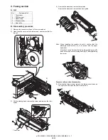
1) Remove the connectors (3 pcs.) of the rear cabinet.
2) Open the side cover, remove two screws, and remove the fus-
ing unit.
3) Cut the binding band, remove the screw, and remove the ther-
mistor.
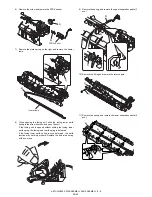
4) Remove the screw and remove the resistor.
Remove the screw and remove the U-turn guide.
Note: When installing the resistor, check to confirm that the
discharge brush section (A) is in contact with the upper
heat roller.
Also check to confirm that the fusing lower earth spring (B)
does not extend over the fusing bearing (C) after tightening
the screw.
Pressure roller section disassembly
5) Remove the three screws, remove the fusing cover lower on
the right side, and open the heat roller section.
No.
Part name Ref.
1
Thermistor
2
PPD2 sensor
3
Heater lamp
4
Pressure roller
5
Heat roller
1)
2)
3)
2)
1)
2)
3)
Thermistor
3)
4)
1)
2)
A
B
C
1)
5)
5)
6)
6)
4)
3)
2)
08/09


