e-STUDIO350/352/353/450/452/453
© 2003 - 2008 TOSHIBA TEC CORPORATION All rights reserved
ADJUSTMENT
3 - 108
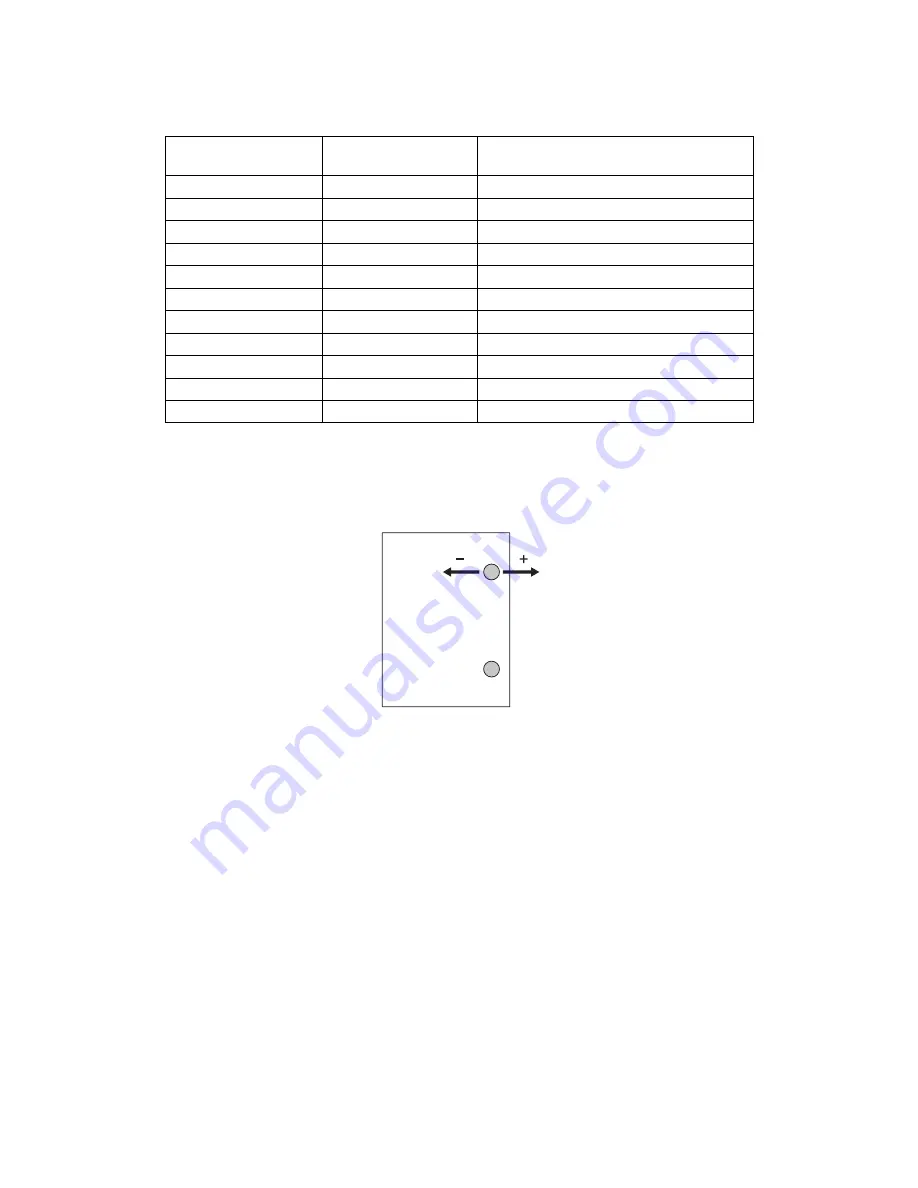
(5) Press Button1 on the finisher control panel to change the adjustment value. The number of times
LED1 blinks changes in ascending order (e.g. 1, 2, 3… 11) each time you press Button1
.
Note:
Note:
When the adjustment value goes further in minus numbers in the table above, the distance
between the paper edge and the holes becomes wider. When it goes further in plus numbers,
this distance becomes narrower.
Fig. 3-148
(6) When the value change is completed, press Button2 on the finisher control panel to determine
the adjustment value. (The adjustment value is written into the flash ROM.)
(7) Turn the power of the equipment OFF.
(8) Turn all the bits of SW1 (DIP-SW) on the finisher control PC board OFF.
(9) Install the board access cover of the Finisher.
Number of LED1’s
blinking
Adjustment value*
Distance moved
1
-5
1.10 mm
2
-4
0.88 mm
3
-3
0.66 mm
4
-2
0.44 mm
5
-1
0.22 mm
6
0
0 mm (Reference position)
7
+1
0.22 mm
8
+2
0.44 mm
9
+3
0.66 mm
10
+4
0.88 mm
11
+5
1.10 mm
06/01


