© 2003 - 2008 TOSHIBA TEC CORPORATION All rights reserved
e-STUDIO350/352/353/450/452/453
ADJUSTMENT
3 - 109
3
3.15 Key Copy Counter (MU-8, MU-10)
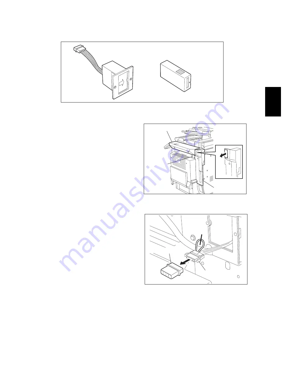
To make a key copy counter available, the following 2 components must be installed to the equipment.
<Installation procedure>
(1) Remove the right upper cover.
(2) Open the bypass tray, ADU, jam access
cover and fuser unit cover. Take off the IH
terminal cover.
(3) Remove the right rear cover, and cut open
the window for the key copy counter.
Fig. 3-149
(4) Pull out the harness connector from the hole
of the machine frame, and cut the short har-
ness of the connector. (Treat the cut harness
properly to avoid it causing a short circuit
with the machine frame.) Then, disconnect
the dummy connector.
Fig. 3-150
Counter socket
MU-10
Key copy counter
MU-8
Right upper cover
IH terminal
cover
Right rear cover
Harness
connector
Dummy connector
04/09


