12
© 2009 TOSHIBA TEC CORPORATION All rights reserved
e-STUDIO182/212/242
FUSER / EXIT UNIT
12 - 19
12.6.6
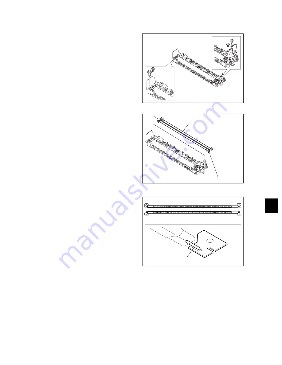
Center heater lamp / Side heater lamp (LAMP1/LAMP2)
(1) Take off the fuser roller unit.
P.12-14 "12.6.2 Pressure roller unit /
Fuser roller unit"
(2) Remove 2 screws on each terminal of both
center heater lamp and side heater lamp.
Fig. 12-25
(3) Pull out the center heater lamp and side
heater lamp.
Notes:
• When installing the heater lamps, be sure
not to mix up the upper heater lamp and
the lower heater lamp.
The upper heater lamp has a coil wound
up on its center part, and the lower heater
lamp has coils wound up on its both
edges.
• When installing the heater lamps, be sure
to face up their weld sides.
• Do not touch the lamps directly with your
hands.
• The connector on each end of the
harness which connects to the center
heater lamp has a small screw hole. The
connector on each end of the harness
which connects to the side heater lamp
has a big one.
Fig. 12-26
Fig. 12-27
Center heater lamp
Side heater lamp
Upper side : center heater lamp
Lower side : side heater lamp
Weld
Summary of Contents for e-studio182
Page 12: ......
Page 18: ...e STUDIO182 212 242 2009 TOSHIBA TEC CORPORATION All rights reserved CONTENTS 6 ...
Page 76: ...e STUDIO182 212 242 2009 TOSHIBA TEC CORPORATION All rights reserved COPY PROCESS 3 14 ...
Page 120: ...e STUDIO182 212 242 2009 TOSHIBA TEC CORPORATION All rights reserved SCANNER 6 26 ...
Page 128: ...e STUDIO182 212 242 2009 TOSHIBA TEC CORPORATION All rights reserved LASER OPTICAL UNIT 7 8 ...
Page 228: ...e STUDIO182 212 242 2009 TOSHIBA TEC CORPORATION All rights reserved FUSER EXIT UNIT 12 24 ...
Page 257: ......
Page 258: ......


