

8
© 2008 - 2011 TOSHIBA TEC CORPORATION All rights reserved
e-STUDIO2020C/2330C/2820C/2830C/3520C/3530C/4520C
FIRMWARE UPDATING
8 - 5
8.1
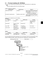
Firmware Updating with USB Media
Firmware can be updated by storing update programs and firmware data files in the USB media.
Note:
When the update is performed, use the latest program.
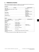
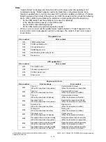
Program necessary for updating
Firmware type and data file name for updating
Equipment
Options
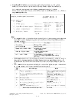
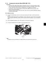
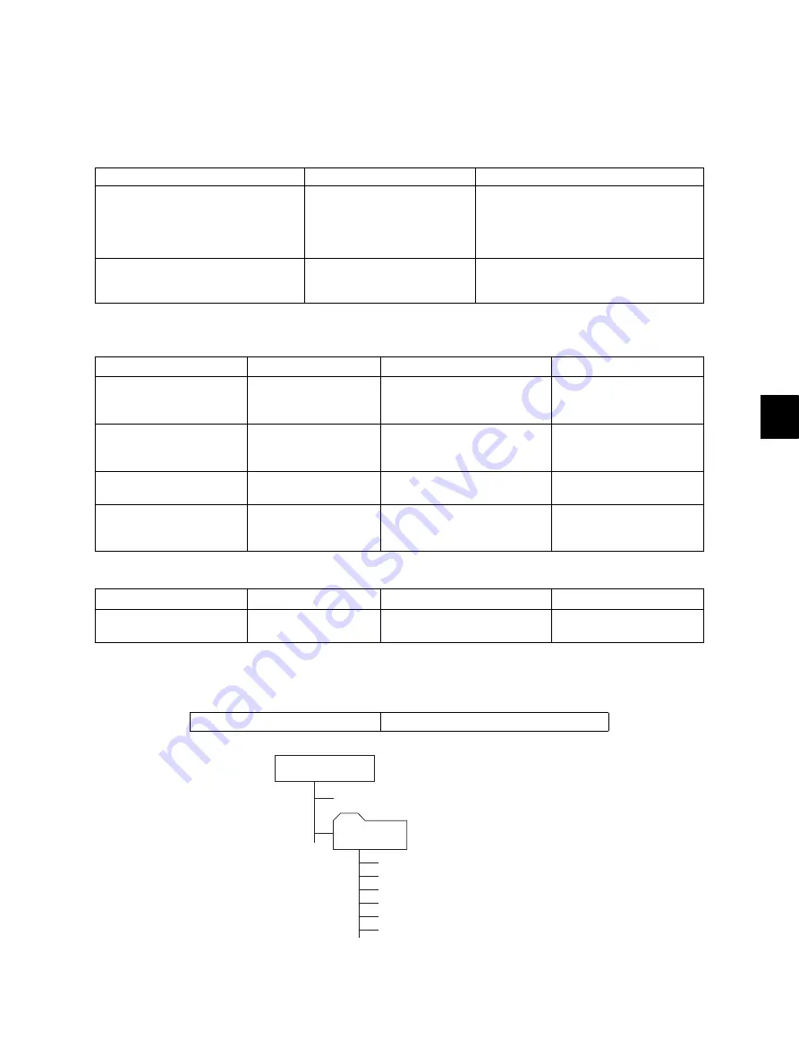
Store the update program loader (mentusb2.o) in the root directory, and store the model specific update
program (dlFirmWare_2820C_3530C) and the data file for updating in the model specific folder.
Fig. 8-1
Update program
Data file name
Remarks
Update program loader
mentusb2.o
An error occurs at a time of the [4] + [9]
startup, unless this program is stored in
the USB media.
*
Be sure to save this data file to the
root directory of the USB media.
Model specific update program
dlFirmWare_2820C_3530C
An error occurs at a time of the [4] + [9]
startup, unless this program is stored in
the USB media.
Firmware
Stored
Data file name
Remarks
Master data
Hard disk
hdd.bin
HDD program data,
System firmware,
UI data
System ROM
System control PC
board
(SYS board)
firmImage0.bin
OS data
Engine ROM
Logic PC board
(LGC board)
T450MWW.xxx
*
xxx is version.
Main firmware
Scanner ROM
Scanning section
control PC board
(SLG board)
T450SLGWW.xxx
*
xxx is version.
Scanner firmware
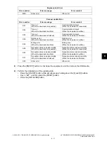
Firmware
Stored
Data file name
Remarks
Imaging Acceleration
Board ROM
Imaging Acceleration
Board (MEP board)
T450IWW.xxx
*
xxx is version.
Imaging Acceleration
Board firmware
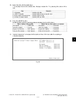
Model specific folder name
2820C_3530C
USB media
2820C_3530C
dlFirmWare_2820C_3530C
mentusb2.o
T450MWW.xxx
T450SLGWW.xxx
firmImage0.bin
hdd.bin
T450IWW.xxx


