2-72
Service Manual
Service checks
Anytime the system board is replaced, the Configuration ID must be reset in NVRAM. Go to
“Configuration ID”
on page 3-21
.
Review the following information before performing any service checks.
•
Paper feed problems (especially paper jams): Go to
“Display Log” on page 3-23
and check the printer
event log for indications of repetitive entries that help to isolate a problem to a particular area of the printer
or option.
•
Paper feed problems with error message: Use the
“Sub error codes for 9xx and 2xx error codes” on
page 2-8
to help diagnose the problem.
•
Print quality problems: Go to
“Print quality pages (Prt Quality Pgs)” on page 3-6
and print a test page to
help diagnose problems before changing any settings or working on the printer.
•
Use the resident diagnostics test provided to help isolate a problem before taking the machine apart or
removing any options.
5-Bin mailbox service check
Service tip: The majority of the mechanical components can be observed during operation by removing the left
and right side covers.
Make sure the option(s) are correctly installed and the machine is configured correctly before attempting to
service the unit.
Problems with excessive static electricity buildup
The printer does not recognize one or more output options as installed
Service tip: If more than a single output option is installed, check each one to see if the printer recognizes any
single option as being installed. If the printer recognizes any of the output options then the base printer
autoconnect system is operating correctly and the problem is in the unrecognized option. Continue with this
service check or go to the service check for the failing output option.
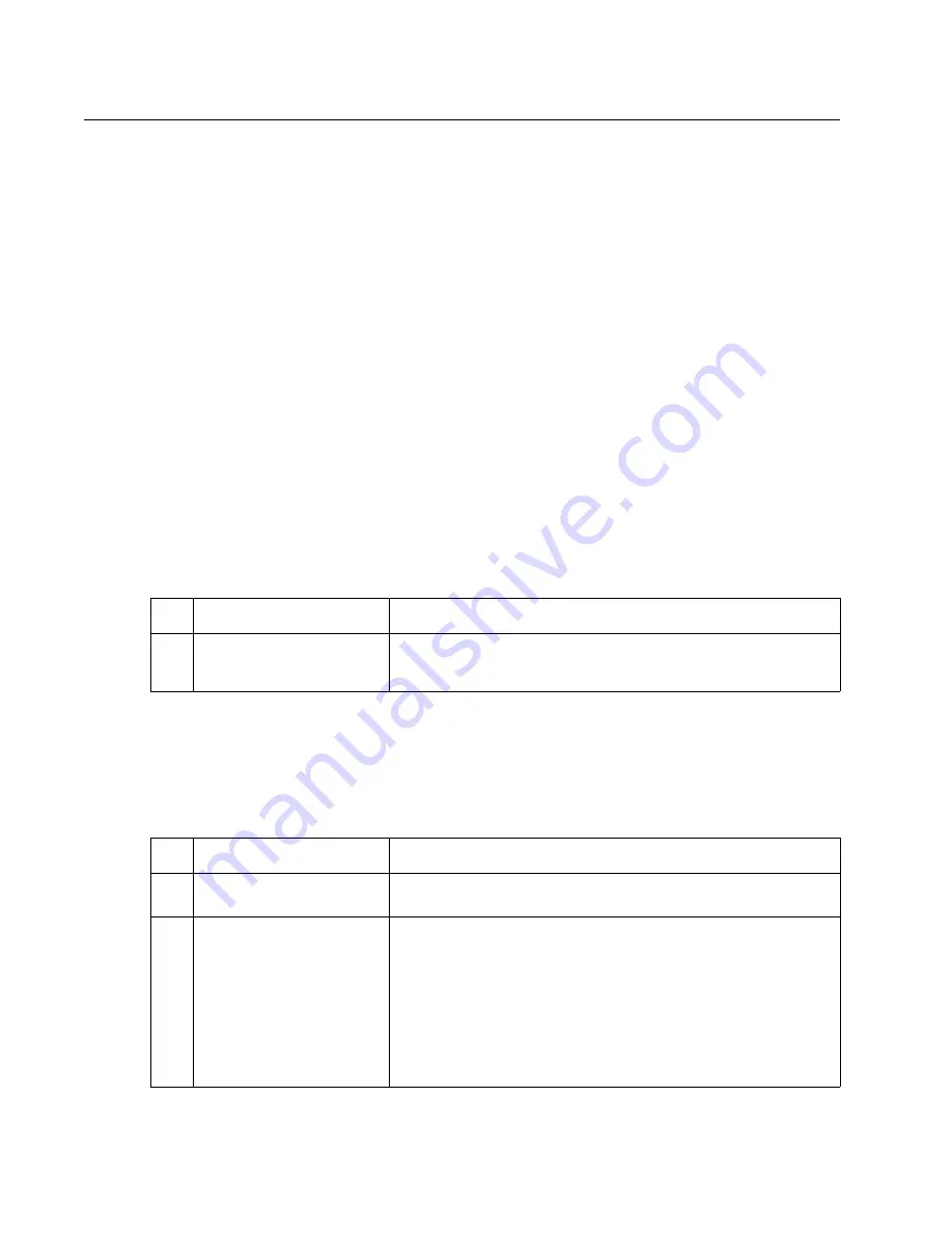
FRU
Action
1
Front cover assembly
Check the front cover assembly to make sure the ESD brush ground
lead is firmly attached to the 5-Bin mailbox frame. Also check to
make sure the ESD brush is not loose or damaged.
FRU
Action
1
5-Bin mailbox option
Check the autoconnects, cables, and connectors of the option for any
signs of loose or damaged parts.
2
Mechanical linkage
assembly
Remove the left and right side covers and check the two
autoconnects for damage, especially the connector pins. Remove the
output option and check the voltages on the standard output bin
autoconnect located on the top left rear of the printer. Go to
“Autoconnect” on page 5-6
. If the voltages are correct, reinstall the
output option noting the position of the toroid on the autoconnect
cable of the lower autoconnect. Check the voltages on each of the
autoconnects. If the toroid was moved, make sure to move it back to
its original position on the cable. If the voltages are correct, replace
the control board. If the voltages are incorrect, replace the failing
autoconnect assembly.
Summary of Contents for e-STUDIO500P
Page 1: ...PRINTER P N 12G9609 e STUDIO500P ...
Page 10: ...x Service Manual ...
Page 15: ...Laser notices xv Japanese Laser Notice ...
Page 16: ...xvi Service Manual Korean Laser Notice ...
Page 43: ...Diagnostic information 2 7 ...
Page 159: ...Diagnostic information 2 123 ...
Page 160: ...2 124 Service Manual ...
Page 161: ...Diagnostic information 2 125 ...
Page 181: ...Diagnostic aids 3 17 ...
Page 297: ...5 12 Service Manual ...
Page 298: ...Connector locations and connections 5 13 ...
Page 299: ...5 14 Service Manual ...
Page 301: ...6 2 Service Manual ...
Page 303: ...7 2 Service Manual Assembly 1 Covers ...
Page 305: ...7 4 Service Manual Assembly 2 Frame 1 ...
Page 307: ...7 6 Service Manual Assembly 3 Frame 2 ...
Page 309: ...7 8 Service Manual Assembly 4 Frame 3 ...
Page 311: ...7 10 Service Manual Assembly 5 Printhead ...
Page 313: ...7 12 Service Manual Assembly 6 Paper feed autocompensator ...
Page 315: ...7 14 Service Manual 4061 xx0 Assembly 7 Paper feed multipurpose feeder ...
Page 317: ...7 16 Service Manual Assembly 8 Paper feed alignment ...
Page 319: ...Page 7 19 has been removed from this document intentionally 7 18 Service Manual ...
Page 320: ...7 20 Service Manual Assembly 10 Integrated 500 sheet paper tray ...
Page 322: ...7 22 Service Manual Assembly 11 Drives Main drive and developer drive ...
Page 324: ...7 24 Service Manual Assembly 12 Hot roll fuser ...
Page 326: ...7 26 Service Manual Assembly 13 Transfer charging ...
Page 328: ...7 28 Service Manual Assembly 14 Electronics power supplies ...
Page 330: ...7 30 Service Manual Note ...
Page 332: ...7 32 Service Manual Assembly 16 Electronics shields ...
Page 336: ...7 36 Service Manual Assembly 19 Cabling diagrams 3 ...
Page 338: ...7 38 Service Manual Assembly 20 Cabling diagrams 4 ...
Page 340: ...7 40 Service Manual Assembly 21 Cabling diagrams 5 ...
Page 342: ...7 42 S ervice Manual THE FOLLOWING PAGE 7 43 HAS BEEN OMITTED FROM THIS MANUAL INTENTIONALLY ...
Page 347: ...7 48 S ervice Manual Pages 7 49 through 7 57 of this manual have been omitted intentionally ...
Page 348: ...7 58 Service Manual Assembly 35 High capacity feeder 1 ...
Page 350: ...7 60 Service Manual Assembly 36 High capacity feeder 2 ...
Page 354: ...7 64 S ervice Manual Pages 7 65 thru 7 70 ofthis manual were omitted intentionally ...
Page 362: ...I 8 Service Manual ...
Page 370: ...I 16 Service Manual ...


