Diagnostic aids
3-1
3. Diagnostic aids
This chapter explains the tests and procedures to identify printer failures and verify repairs have corrected the
problem.
Accessing service menus
There are different test menus that can be accessed during POR to identify problems with the printer.
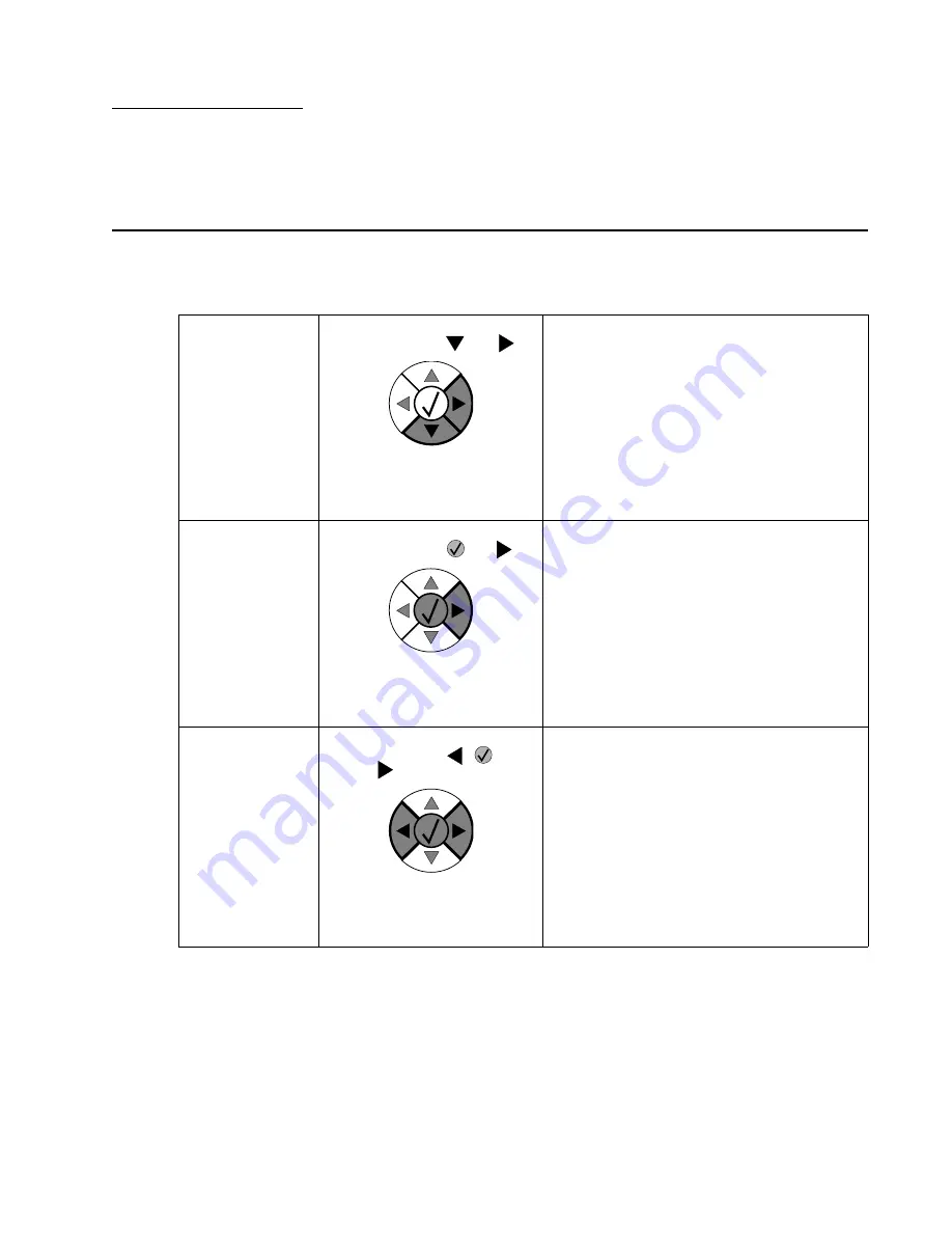
To run the printer diagnostic tests described in this chapter, you must put the printer in Diagnostic Mode.
Diagnostics Mode
1. Turn off the printer.
2. Press and hold
and
.
3. Turn on the printer.
4. Release the buttons when
Performing Self Test
displays.
The Diagnostics Mode group contains the settings
and operations used while manufacturing and
servicing the printer.
See
“Diagnostics mode” on page 3-2
for more
information.
Configuration Menu
1. Turn off the printer.
2. Press and hold
and
.
3. Turn on the printer.
4. Release the buttons when
Performing Self Test
displays.
The Configuration Menu group contains a set of
menus, settings, and operations which are
infrequently required by a user. Generally, the
options made available in this menu group are
used to configure a printer for operation.
See
“Configuration menu (CONFIG MENU)” on
page 3-25
for more information.
Flash system code
mode
1. Turn off the printer.
2. Press and hold
,
,
and
.
3. Turn on the printer.
4. Release the buttons when
Performing Self Test
displays.
Summary of Contents for e-STUDIO500P
Page 1: ...PRINTER P N 12G9609 e STUDIO500P ...
Page 10: ...x Service Manual ...
Page 15: ...Laser notices xv Japanese Laser Notice ...
Page 16: ...xvi Service Manual Korean Laser Notice ...
Page 43: ...Diagnostic information 2 7 ...
Page 159: ...Diagnostic information 2 123 ...
Page 160: ...2 124 Service Manual ...
Page 161: ...Diagnostic information 2 125 ...
Page 181: ...Diagnostic aids 3 17 ...
Page 297: ...5 12 Service Manual ...
Page 298: ...Connector locations and connections 5 13 ...
Page 299: ...5 14 Service Manual ...
Page 301: ...6 2 Service Manual ...
Page 303: ...7 2 Service Manual Assembly 1 Covers ...
Page 305: ...7 4 Service Manual Assembly 2 Frame 1 ...
Page 307: ...7 6 Service Manual Assembly 3 Frame 2 ...
Page 309: ...7 8 Service Manual Assembly 4 Frame 3 ...
Page 311: ...7 10 Service Manual Assembly 5 Printhead ...
Page 313: ...7 12 Service Manual Assembly 6 Paper feed autocompensator ...
Page 315: ...7 14 Service Manual 4061 xx0 Assembly 7 Paper feed multipurpose feeder ...
Page 317: ...7 16 Service Manual Assembly 8 Paper feed alignment ...
Page 319: ...Page 7 19 has been removed from this document intentionally 7 18 Service Manual ...
Page 320: ...7 20 Service Manual Assembly 10 Integrated 500 sheet paper tray ...
Page 322: ...7 22 Service Manual Assembly 11 Drives Main drive and developer drive ...
Page 324: ...7 24 Service Manual Assembly 12 Hot roll fuser ...
Page 326: ...7 26 Service Manual Assembly 13 Transfer charging ...
Page 328: ...7 28 Service Manual Assembly 14 Electronics power supplies ...
Page 330: ...7 30 Service Manual Note ...
Page 332: ...7 32 Service Manual Assembly 16 Electronics shields ...
Page 336: ...7 36 Service Manual Assembly 19 Cabling diagrams 3 ...
Page 338: ...7 38 Service Manual Assembly 20 Cabling diagrams 4 ...
Page 340: ...7 40 Service Manual Assembly 21 Cabling diagrams 5 ...
Page 342: ...7 42 S ervice Manual THE FOLLOWING PAGE 7 43 HAS BEEN OMITTED FROM THIS MANUAL INTENTIONALLY ...
Page 347: ...7 48 S ervice Manual Pages 7 49 through 7 57 of this manual have been omitted intentionally ...
Page 348: ...7 58 Service Manual Assembly 35 High capacity feeder 1 ...
Page 350: ...7 60 Service Manual Assembly 36 High capacity feeder 2 ...
Page 354: ...7 64 S ervice Manual Pages 7 65 thru 7 70 ofthis manual were omitted intentionally ...
Page 362: ...I 8 Service Manual ...
Page 370: ...I 16 Service Manual ...


