Index
I-1
Index
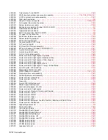
Numerics
1565 Emul Error Load Emul Option
2-42
250-sheet paper drawer, option
7-42
250-sheet paper tray, integrated
7-18
250-sheet paper tray, option
parts catalog
7-43
service check
2-102
2
xx
paper jam and paper handing errors
2-44
500-sheet paper drawer, option
7-44
500-sheet paper tray, option
parts catalog
7-45
service check
2-102
5-bin mailbox
output sensor test
3-16
parts catalog
7-54
,
7-56
service check
2-72
80 scheduled maintenance
6-1
900.xx error code service check
2-75
927.xx fan service check
2-76
950.00 through 950.29 EPROM mismatch failure
2-77
950.30 through 950.60 EPROM mismatch failure
2-78
9
xx
Service error codes
2-8
A
acronyms
1-20
adjustments
fuser solenoid
4-2
gap adjustment
4-2
paper alignment assembly
4-3
printhead assembly
4-2
alignment assembly
adjustment
4-3
parts catalog
7-16
removal
4-68
autocompensator, integrated tray
parts catalog
7-12
pick roll installation
4-52
removal
4-49
autoconnect connections, top
5-6
B
bevel gear
installation
4-22
removal
4-21
bezel, operator panel
4-14
blower duct
7-9
Button Test
3-7
buttons
accessing service menus
3-1
Button Test
3-7
description function
2-2
operator panel button removal
4-67
upper front cover including buttons
7-3
upper front panel button kit
7-3
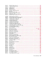
C
cable diagrams
7-34
,
7-35
,
7-36
,
7-38
,
7-40
CACHE Test
3-8
Card Stock & Label Guide
1-8
card stock, guidelines
1-18
cartridge duct, removal
4-23
characteristics, print media
1-15
code update
3-1
Configuration ID
3-21
configuration menu
accessing
3-1
,
3-25
available menus
3-25
Demo Mode
3-27
Disk Encryption
3-28
Download Emuls
3-27
Energy Conserve
3-28
Env Prompts
3-28
EVENT LOG
3-28
Factory Defaults
3-28
Font Sharpening
3-29
Jobs On Disk
3-28
LCD Brightness
3-29
LCD Contrast
3-29
Maint Cnt Value
3-25
Panel Menus
3-27
Paper Prompts
3-28
PPDS Emulation
3-27
Prt Quality Pgs
3-26
Reset Maint Cnt
3-26
SIZE SENSING
3-27
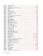
configurations, models
1-2
connector locations
autoconnect - top
5-6
high voltage power supply (HVPS)
5-9
high-capacity output stacker board
5-8
interconnect card
5-9
low voltage power supply (LVPS)
5-10
output expander
5-11
StapleSmart finisher
5-12
system board
5-1
cover closed switch
2-80
covers
parts catalog
7-2
removals
4-4
D
defaults
EP defaults
3-22
factory defaults
3-28
US/Non-US defaults
3-20
deflector
inner paper deflector assembly
4-47
MPF lower paper deflector
4-61
upper paper deflector assembly
4-79
Summary of Contents for e-STUDIO500P
Page 1: ...PRINTER P N 12G9609 e STUDIO500P ...
Page 10: ...x Service Manual ...
Page 15: ...Laser notices xv Japanese Laser Notice ...
Page 16: ...xvi Service Manual Korean Laser Notice ...
Page 43: ...Diagnostic information 2 7 ...
Page 159: ...Diagnostic information 2 123 ...
Page 160: ...2 124 Service Manual ...
Page 161: ...Diagnostic information 2 125 ...
Page 181: ...Diagnostic aids 3 17 ...
Page 297: ...5 12 Service Manual ...
Page 298: ...Connector locations and connections 5 13 ...
Page 299: ...5 14 Service Manual ...
Page 301: ...6 2 Service Manual ...
Page 303: ...7 2 Service Manual Assembly 1 Covers ...
Page 305: ...7 4 Service Manual Assembly 2 Frame 1 ...
Page 307: ...7 6 Service Manual Assembly 3 Frame 2 ...
Page 309: ...7 8 Service Manual Assembly 4 Frame 3 ...
Page 311: ...7 10 Service Manual Assembly 5 Printhead ...
Page 313: ...7 12 Service Manual Assembly 6 Paper feed autocompensator ...
Page 315: ...7 14 Service Manual 4061 xx0 Assembly 7 Paper feed multipurpose feeder ...
Page 317: ...7 16 Service Manual Assembly 8 Paper feed alignment ...
Page 319: ...Page 7 19 has been removed from this document intentionally 7 18 Service Manual ...
Page 320: ...7 20 Service Manual Assembly 10 Integrated 500 sheet paper tray ...
Page 322: ...7 22 Service Manual Assembly 11 Drives Main drive and developer drive ...
Page 324: ...7 24 Service Manual Assembly 12 Hot roll fuser ...
Page 326: ...7 26 Service Manual Assembly 13 Transfer charging ...
Page 328: ...7 28 Service Manual Assembly 14 Electronics power supplies ...
Page 330: ...7 30 Service Manual Note ...
Page 332: ...7 32 Service Manual Assembly 16 Electronics shields ...
Page 336: ...7 36 Service Manual Assembly 19 Cabling diagrams 3 ...
Page 338: ...7 38 Service Manual Assembly 20 Cabling diagrams 4 ...
Page 340: ...7 40 Service Manual Assembly 21 Cabling diagrams 5 ...
Page 342: ...7 42 S ervice Manual THE FOLLOWING PAGE 7 43 HAS BEEN OMITTED FROM THIS MANUAL INTENTIONALLY ...
Page 347: ...7 48 S ervice Manual Pages 7 49 through 7 57 of this manual have been omitted intentionally ...
Page 348: ...7 58 Service Manual Assembly 35 High capacity feeder 1 ...
Page 350: ...7 60 Service Manual Assembly 36 High capacity feeder 2 ...
Page 354: ...7 64 S ervice Manual Pages 7 65 thru 7 70 ofthis manual were omitted intentionally ...
Page 362: ...I 8 Service Manual ...
Page 370: ...I 16 Service Manual ...


