Diagnostic information
2-39
37
.xx
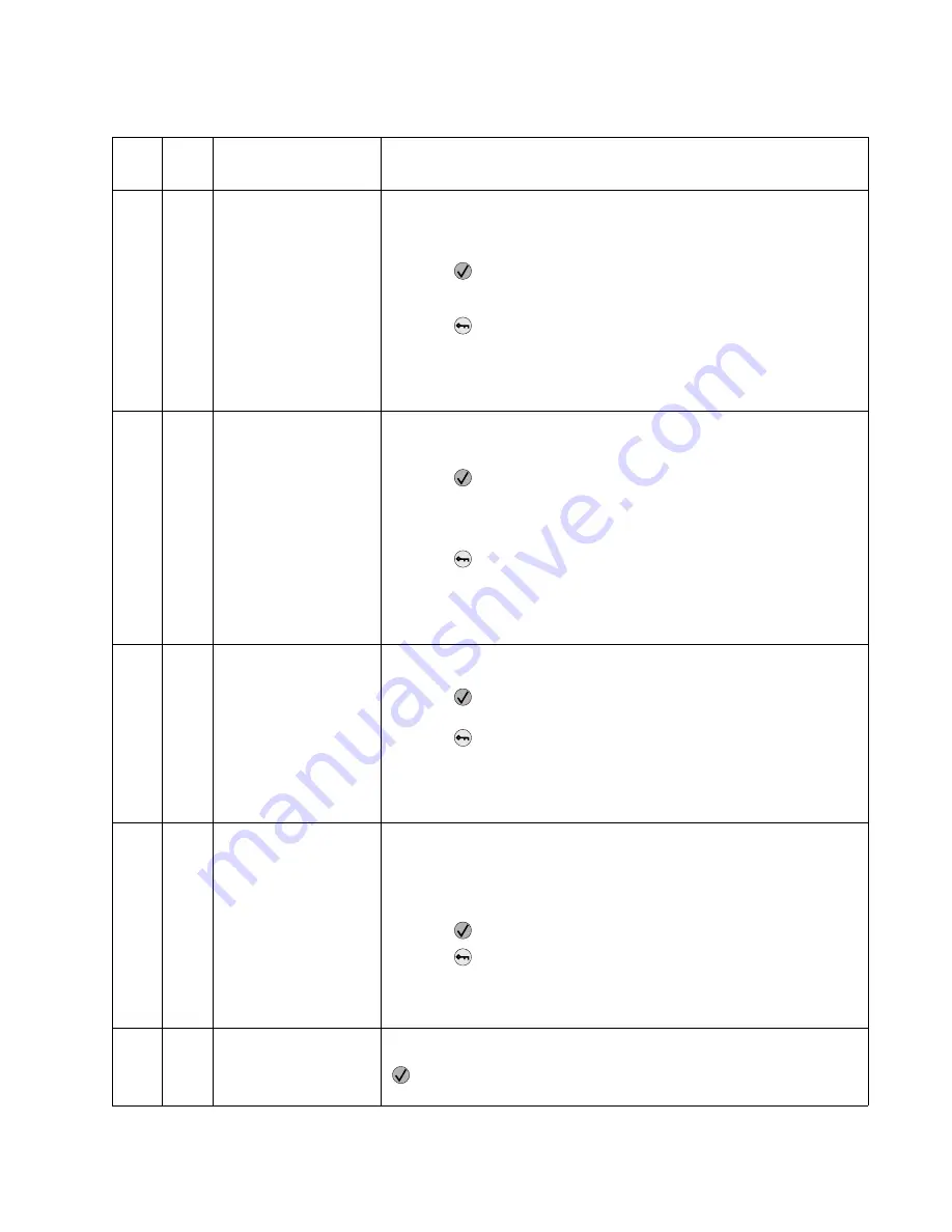
Insufficient Memory
This message displays when the printer memory used to restore the Print
and Hold jobs from the disk and found that some or all of the jobs could not
be restored. The printer ran out of memory while attempting to restore the
jobs.
• Press
to clear the message. Some of the Print and Hold jobs on the
disk will not be restored. They remain on the disk, but cannot be
accessed.
• Press
until Busy/Waiting appears. The following functions may be
available:
- Cancel Job
- Reset Printer
- Reset Active Bin
38
.xx
Memory Full
This message displays when the printer is processing an incoming job and
there is insufficient memory available to continue processing the job. The
following actions may be taken:
• Press
to clear the message. Perform the defragment operation:
- Perform the defragment operation
- Delete fonts, macros, and other data in RAM
- Install additional memory
• Press
to display Busy/Waiting. The following functions may be
available:
- Cancel Job
- Reset Printer
- Reset Active Bin
39
.xx
Complex Page
This message displays when the page is too complex to print. The following
actions may be taken:
• Press
to clear the message and continue the job. Some data loss
may occur. Simplify the print job and reprint, if necessary.
• Press
until Busy/Waiting appears. The following selections are
possible:
- Cancel Job
- Reset Printer
- Reset Active Bin
50
.xx
PPDS Font Error
This message displays when the PPDS interpreter has encountered a font
error.
Note:
This error may only occur when the printer is formatting PPDS print
data.
The following actions may be taken:
• Press
to clear the message and continue processing the job.
• Press
until Busy/Waiting appears. The following are available:
- Cancel Job
- Reset Printer
- Reset Active Bin
51
.xx
Defective Flash
This message displays when the printer detects a defective flash. This error
may occur at power on, or during flash format and write operations. Press
to clear the message. The flash is marked as bad and normal operation
continues. Flash operations are not allowed until the problem is resolved.
User attendance messages (continued)
Error
code
Sub
code
Primary message
Description/action
Summary of Contents for e-STUDIO500P
Page 1: ...PRINTER P N 12G9609 e STUDIO500P ...
Page 10: ...x Service Manual ...
Page 15: ...Laser notices xv Japanese Laser Notice ...
Page 16: ...xvi Service Manual Korean Laser Notice ...
Page 43: ...Diagnostic information 2 7 ...
Page 159: ...Diagnostic information 2 123 ...
Page 160: ...2 124 Service Manual ...
Page 161: ...Diagnostic information 2 125 ...
Page 181: ...Diagnostic aids 3 17 ...
Page 297: ...5 12 Service Manual ...
Page 298: ...Connector locations and connections 5 13 ...
Page 299: ...5 14 Service Manual ...
Page 301: ...6 2 Service Manual ...
Page 303: ...7 2 Service Manual Assembly 1 Covers ...
Page 305: ...7 4 Service Manual Assembly 2 Frame 1 ...
Page 307: ...7 6 Service Manual Assembly 3 Frame 2 ...
Page 309: ...7 8 Service Manual Assembly 4 Frame 3 ...
Page 311: ...7 10 Service Manual Assembly 5 Printhead ...
Page 313: ...7 12 Service Manual Assembly 6 Paper feed autocompensator ...
Page 315: ...7 14 Service Manual 4061 xx0 Assembly 7 Paper feed multipurpose feeder ...
Page 317: ...7 16 Service Manual Assembly 8 Paper feed alignment ...
Page 319: ...Page 7 19 has been removed from this document intentionally 7 18 Service Manual ...
Page 320: ...7 20 Service Manual Assembly 10 Integrated 500 sheet paper tray ...
Page 322: ...7 22 Service Manual Assembly 11 Drives Main drive and developer drive ...
Page 324: ...7 24 Service Manual Assembly 12 Hot roll fuser ...
Page 326: ...7 26 Service Manual Assembly 13 Transfer charging ...
Page 328: ...7 28 Service Manual Assembly 14 Electronics power supplies ...
Page 330: ...7 30 Service Manual Note ...
Page 332: ...7 32 Service Manual Assembly 16 Electronics shields ...
Page 336: ...7 36 Service Manual Assembly 19 Cabling diagrams 3 ...
Page 338: ...7 38 Service Manual Assembly 20 Cabling diagrams 4 ...
Page 340: ...7 40 Service Manual Assembly 21 Cabling diagrams 5 ...
Page 342: ...7 42 S ervice Manual THE FOLLOWING PAGE 7 43 HAS BEEN OMITTED FROM THIS MANUAL INTENTIONALLY ...
Page 347: ...7 48 S ervice Manual Pages 7 49 through 7 57 of this manual have been omitted intentionally ...
Page 348: ...7 58 Service Manual Assembly 35 High capacity feeder 1 ...
Page 350: ...7 60 Service Manual Assembly 36 High capacity feeder 2 ...
Page 354: ...7 64 S ervice Manual Pages 7 65 thru 7 70 ofthis manual were omitted intentionally ...
Page 362: ...I 8 Service Manual ...
Page 370: ...I 16 Service Manual ...


