FC-22
TROUBLESHOOTING
4 - 50
January 2000 © TOSHIBA TEC
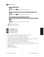
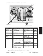
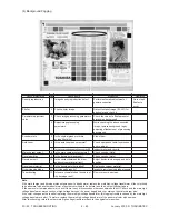
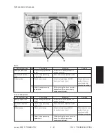
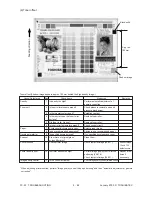
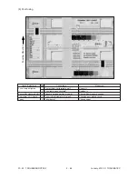
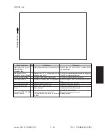
<Check by grid pattern>
13.While pressing [0] and [5] simultaneously, turn the power ON.
14.Input [1] with digital key and press [SETTINGS].
15.Check that there is no image density difference among the front/center/rear areas of the
output grid pattern for each of yellow, magenta, cyan and black. Check that there is no
abnormality in the overall image.
* At this point, there is no problem if the Y, M, C and K grid patterns are out of alignment.
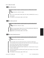
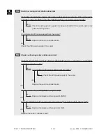
– If there is difference in tonal balance between front and rear area –
• Check the state of contact of the photoconductive drum and the transfer belt.
• Check the quantity of developer (check whether developer material is properly sup-
plied onto the surface of the developer sleeve).
– If there is any yellow, magenta, cyan or black streak in the secondary scanning direc-
tion –
• Check if there is any stain or dust on the main charger wire that corresponds to the
color of the streak.
– If there is any white streak in the secondary scanning direction –
• Check if there is any stain or dust on the slit glass of the laser optical unit.
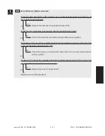
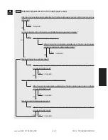
– If the entire page is solid in a specific color –
• Defect in main high-voltage transformer corresponding to that color or defect in the
laser optical unit.
Of the four main high-voltage transformers, replace the main high-voltage trans-
former considered to be defective with other main high-voltage transformer consid-
ered to be normal, and then output the chart again.
If the solid color over the entire page changes as the result of replacing the main
high-voltage transformer, that main high-voltage transformer replaced is defective.
If the solid color over the entire page does not change, check whether there is any
disconnection of the harness between the LGC board and the main high-voltage
transformer or any defects in the power supply to the main charger (disconnection
of high-voltage harness or contact defects). if there is no problem, check the laser
optical unit.
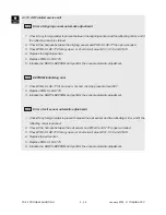
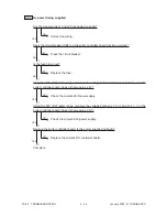
If the density is low on both front and rear sides and any of the above abnormalities are not
found, make the following check.
Summary of Contents for FC22
Page 115: ...FC 22 PREVENTIVE MAINTENANCE 2 8 January 2000 TOSHIBA TEC Front side drive system 47 20 ...
Page 121: ......
Page 235: ...January 2000 TOSHIBA TEC 5 29 FC 22 FIRMWARE UPDATING ...
Page 237: ...FC 22 SERVICE HANDBOOK 6 WIRE HARNESS CONNECTION DIAGRAMS 6 2 DC Wire Harness ...
Page 238: ...FC 22 WIREHARNESS CONNECTION DIAGRAMS 6 3 January 20000 TOSHIBA TEC ...

