G2020 MMS KIT Installation Manual
– 4GBH0111A
15
APPENDIX A Parallel operation system connection
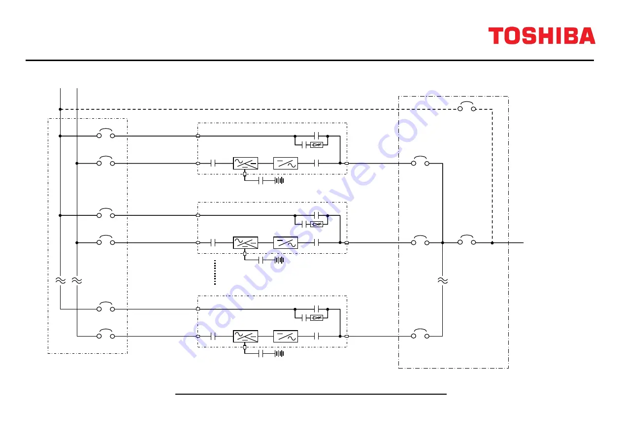
Figure A-1 Diagram of power wire connections (Parallel system configuration)
52L1
UPS
Breaker
52L2
UPS
Breaker
Toshiba Tie Cabinet (TTC)
52Ln (*1)
UPS
Breaker
52MB
Maintenance
Bypass
Breaker
52CS
Output
Breaker
Bypass input
AC input
Bypass input
AC input
Bypass input
AC input
AC output
(*1) n: Maximum=8
AC output
AC output
CB2
Inverter
CB1
UPS-1
Battery
52C
Converter
/Charger
52S
CB2
Inverter
CB1
UPS-2
Battery
52C
Converter
/Charger
52S
CB2
Inverter
CB1
UPS-n
Battery
52C
Converter
/Charger
52S


