background image

TOSHIBA 

6F3H1048 

9.2 

Key-Switch and  Buttons 

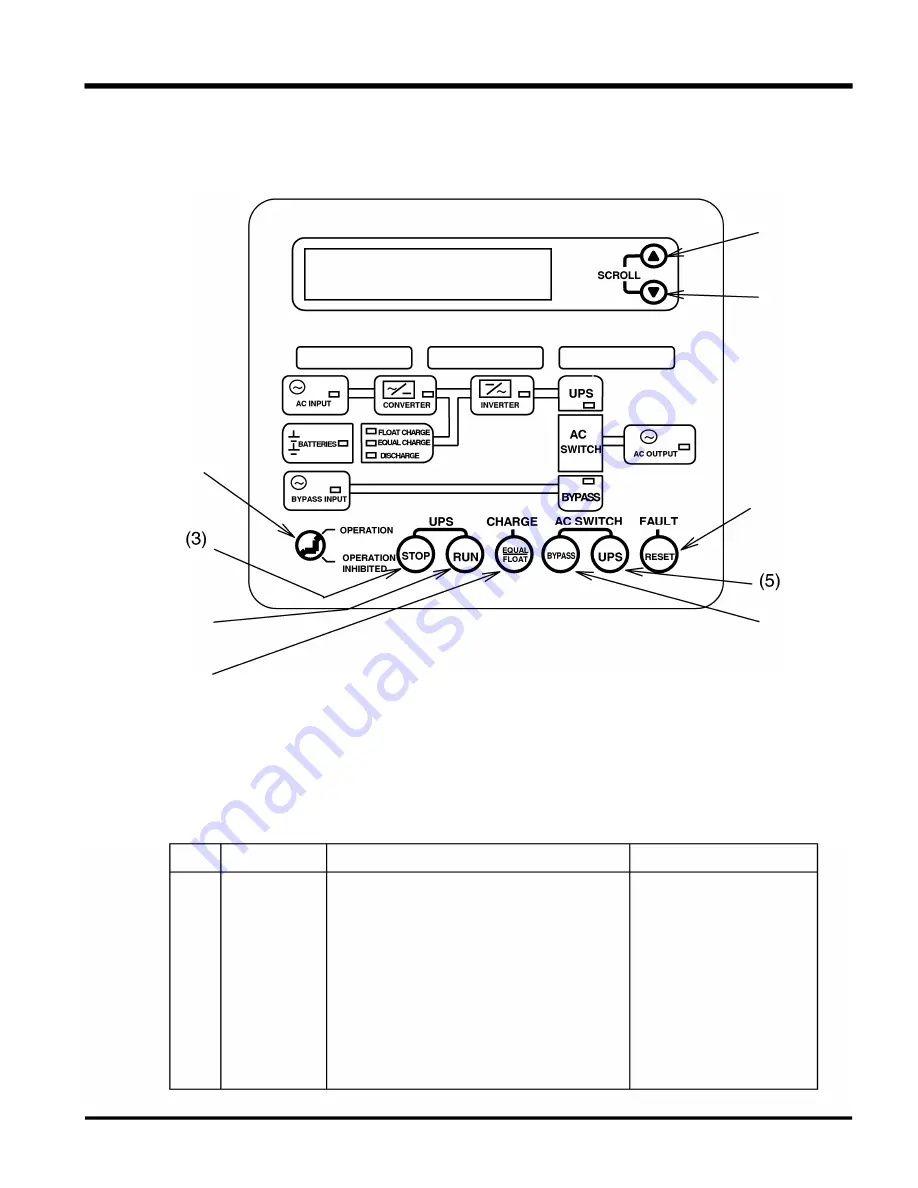
The  key-switch  and  operating  buttons  on  the  graphic  panel  are  shown  in  Figure  9.2. 1 .  See 
section 9.2 . 1   " Key-switch" and section 9.2.2 "Operating buttons" for each function. 

(7) 

(8) 

[YBSSUPPLY 

OtARNING 

DAULT 

(1 ) 

(9) 

(2) 

(4) 

(6) 

9.2.1 

Key-switch 

Figure 9.2.1 

Graphic Panel 

Table 9.2 shows the function of the key-switch on the graphic panel. 

Table 9.2 Key-switch fu nction 

No. 

Name 

Function 

Remarks 

(1 ) 

OPERATION 

This key-switch enables operation buttons 

The key-switch at the 

LOCK 

pressed when it is in  "OPERATION" mode. 

"OPERATION INHIBITED" 

When the key-switch is at "OPERATION 

can eliminate misoperation 

INHIBITED" mode,  the operation is disabled, 

procedures. 

and buttons (2) 

-

(6) 

and (9) shown in Table 

9.3 are not operative. They have no effect 
upon the  UPS operation. 

LCD scroll buttons (7) and 

(8) 

still work 

regardless of the key-switch position. 

- 25 -

www 

. ElectricalPartManuals 

. com

Summary of Contents for G8000U Series

Page 1: ... operation manual carefully before operating the UPS 2 Place this manual close to the UPS to be able to refer to whenever necessary 3 This manual should be distributed to the proper personnel who will operate and or maintain the UPS July 2003 6F3H1048 w w w E l e c t r i c a l P a r t M a n u a l s c o m ...

Page 2: ... designed to ensure the safe and correct operation of the G8000 UPS Please read through all of the chapters before operation Above all read the General safety instructions Important safety instructions Safety Precautions and Operation chapters as these must be carefully read Please make sure you have a thorough understanding of the information in these 4 chapters Personnel who will install operate...

Page 3: ...D also occur CAUTION 4 Attention The attention warning symbol is an exclamation mark enclosed in a triangle which precedes the word ATTENTION The attention symbol is used to indicate situations and conditions that COULD cause operator injury and or equipment damage ATTENTION Other warning symbols may appear along with the Danger and Caution symbols The additional symbols are used to specify specia...

Page 4: ...AC input or Bypass input and power sources The minimum device ratings should be as follows Model 1 50kVA 300kVA Rated Input 4BOV 277Vac 4BOV 277Vac Breaker Rating 4BOV 225A 4BOV 500A Model 225kVA Rated Input 4BOV 277Vac Breaker Rating 4BOV 350A The maximum ambient temperatures in which the UPS should be operated is 40 C 1 04 F and 32 C gO F maximum if the battery system is subject to the same ambi...

Page 5: ...ances Equipment equivalent to the above Equipment to supervise or control airways railways roads sea lanes or other transportation Equipment in nuclear power plants Equipment to control communications Equipment equivalent similar to the above mentioned Disclaimer In no event will Toshiba Corporation be responsible or liable for either indirect or consequential damage or injury that may come from t...

Page 6: ...r and or may result in electric shock or personal injury Do NOT modify the UPS relocate after initial installation or replace parts by untrained personnel Electrical shock injury or UPS faults may happen if non certified technicians attempt to modify or relocate the UPS Please contact Toshiba if you need UPS modifications or plan to move the UPS Do NOT open the front cover There are energy high cu...

Page 7: ...ce with the customers requirements 6F3H1048 PROHIBITED Make sure the air vents on the front and top of the UPS are not blocked Blocking the vents will cause the temperature inside the UPS to rise and may result in fire or UPS faults Please understand what the warning labels state and follow the warnings or procedures indicated on these labels Operating the equipment without thorough understanding ...

Page 8: ... Intended for installation in a controlled environment CAUTION 8A control power source switch Do not turn off while operating 300kVA DANGER RISK OF ELECTRIC SHOCK This UPS receive power from more than one source disconnection of all sources is required to de energize this unit before servicing Dangerous electric charge may be stored in capacitors and associated circuitry Wait at least five 5 minut...

Page 9: ...nt High temperature humidity may shorten the life of components within the UPS Do NOT install the UPS close to a water source It may cause electrical shock UPS fault or other accidents Please ask Toshiba or authorized representatives when the UPS and or components are to be disposed It may be illegal to dispose of certain components without conforming to environmental regulation for industrial com...

Page 10: ...rminal only Missing ground wire may cause electrical shock Connecting to more than one ground may cause ground loop Refer to the installation manual for ground wiring details 9 6F3H1048 o MANDATORY w w w E l e c t r i c a l P a r t M a n u a l s c o m ...

Page 11: ...2 Please read all warning labels and understand what they mean 3 Make sure warning labels are always legible Do NOT allow them be removed or covered up Locations of the Warning Labels 150 225 kVA _ B D RATING NP D D Locations of the Warning Labels 300 kVA D D Figure 5 1 UPS exterior interior showing warning labels 10 w w w E l e c t r i c a l P a r t M a n u a l s c o m ...

Page 12: ...om more than one source disconnection of all sources is required to de energize this unit before servicing Dangerous electric charge may be stored in capacitors and associated circuitry Wait at least five 5 minutes for power to dissipate then check voltage before servicing OANGER RISK OF ELECTRIC SHOCK Capacitors stay charged after power has been shut off Accidental contact with live parts can cau...

Page 13: ...TORS ONLY REFER TO INSTRUCTION MANUAL REGARDING TIGHTENING TORQUE OF TERMINAL BLOCKS 480V 400V 480V AC INPUT BATTERY BYPASS INPUT 480V AC OUTPUT The label G is attached at the ground wire connection point CD CAUTION RISK OF ELECTRIC SHOCK Heat Sink IGBT is not grounded Test before touching Q CAUTION 8A control power source switch Do not turn off while operating The label E is mounted in the vicini...

Page 14: ...ff the air conditioner will cause high temperatures and may result in an UPS fault High temperatures shorten the life of components within the UPS and battery systems 6F3H1048 Please operate the UPS using the procedures described in Chapter 1 0 Operation while referring to the instruction information on graphic panel LCD Operation procedures other than specified may result in an UPS fault The star...

Page 15: ...y give an electrical shock 0 PROHIBITED Do NOT operate the UPS in wet locations Operation in wet location may cause electrical shock UPS 0 fault or other accidents PROHIBITED Keep the reset button pressed for 5 seconds to reset the UPS The UPS may not be reset if the duration is too short 0 MANDATORY 14 w w w E l e c t r i c a l P a r t M a n u a l s c o m ...

Page 16: ... LED Indication 10 2 LCD Indication 1 0 2 1 Normal Display 1 0 2 2 Fault Display 1 0 2 3 Warning Display 1 0 2 4 LCD Scroll 1 1 Operation 11 1 Operation Types 11 2 Pre operational check 11 3 Procedures 1 1 3 1 Startup 1 1 3 2 Switch Power Supply UPS Bypass 1 1 3 3 Stop 1 1 3 4 Complete Shutdown 1 1 3 5 Changing Between Float Charge and Equalize Charge 1 1 3 6 Changing to Float Charge from Protecti...

Page 17: ...creen 1 2 2 3 Fault Messages 1 2 2 4 LCD scroll with faults or warnings 12 3 Restoring UPS Operation 1 3 UPS Specification 13 1 General Specification 13 2 Mechanical Specification 13 3 Electrical Specification Appendix 16 6F3H1048 44 44 45 45 46 47 49 51 52 52 52 53 54 w w w E l e c t r i c a l P a r t M a n u a l s c o m ...

Page 18: ...vering the vents will cause the temperature inside the UPS to rise and may result in fire and or UPS faults Figure 8 1 shows the outline dimensions of the 150kVA 225kVA UPS 1 S RATING NP Terminal Blocks I 1400 SS 1 1 3 71 Weight 1 SOOkg 3 300Ibs l 11 70 46 15 74 8 0 SWITCH EP O SWITCH B A i Termina l Block Control Earth Ground Bus t 8 0 0 31 S II Figure 8 1 1 50 225kVA UPS Exterior dimensions fron...

Page 19: ...nrl R _Li u T ln d tI T TERMINAL BUS RATING NP TERMINAL BLOCKS CONTROL SWITCH e EPO e 74 8 SWITCH SA 6F3H1048 900 354 QL JQ 8 16 DIA H OLE 3 9 Earth Ground FRONT VIEW Rile 1 125 I 650 J 125 S I DE VI EW RIGHT Figure 8 2 300kVA UPS Exterior dimensions front right side 18 w w w E l e c t r i c a l P a r t M a n u a l s c o m ...

Page 20: ...htening torque must be greater than 90 percent of the recommended torque Cable Size and Tightening Torque for 150kVA UPS Only copper wires allowed Block Number Cable Size Tightening Torque 1 AWG 3 0 or larger 275 in Ibs 2 AWG 3 0 or larger 275 in Ibs 3 AWG 3 0 or larger 275 in Ibs 4 AWG 3 0 or larger 275 in Ibs 5 AWG 3 0 or larger 275 in Ibs 6 AWG 3 0 or larger 275 in Ibs 7 AWG 3 0 or larger 275 i...

Page 21: ...0MCM or larger 500 in Ibs 10 300MCM or larger 500 in Ibs 11 300MCM or larger 500 in Ibs 12 Two 300MCM or larger 500 in Ibs 13 Two 300MCM or larger 500 in Ibs NOTE Maximum cable size is 500MCM 3 cable knockout plates are provided at bottom of the 150 225kVA UPS Holes are recommended in Figure 8 3 The 5 holes must be punched by the installing electrical contractor 0 8 Plate 1 Plate 2 Plate 3 r I 4 D...

Page 22: ...Tightening Torque for 300kVA UPS The tightening torque must be greater than 90 percent of the recommended torque Cable Size and Tightening Torque at 300kVA UPS Terminals Bus Number Cable Size Torque to tighten Only copper wires allowed the terminal bus 1 Two 3 0 AWG or larger 215 386 in Ibs 2 Two 3 0 AWG or larger 215 386 in Ibs 3 Two 3 0 AWG or larger 215 386 in Ibs 4 Three 350MCM or larger 215 3...

Page 23: ...8 4 The 6 holes must be punched by the installing electrical contractor Plate 1 12 Dia l I I I I J __ I 0 6 Ground Wire 1 5 0 4 Plate 2 Plate 3 Plate 4 I 4 Dia I I 1 __ i___________ 0 8 AC Input Battery I I I I ______ 1 Bypass AC Output 12 Dia I I I I I _ L_ I 0 6 Control Wires 4 solid rectangles show the cable knockout plates outline The 3 dashed rectangles show the UPS opening under the plates F...

Page 24: ...or Authorized representatives 9 1 Operating Switches Figure 9 1 and Table 9 1 show the location and functions of the operating switches to operate the UPS circuit shown in Figures 9 2 NOTES Do NOT turn off the control power source switch SA during UPS operation This may result in UPS faults Figure 9 1 Operating Switches 23 EPO Switch SA Switch w w w E l e c t r i c a l P a r t M a n u a l s c o m ...

Page 25: ...this switch is pressed UPS will stop Switch operation and all the breakers will be tripped opened BYPASS S3BF INPUT O _ou 2R I l AC INPUT O I RECTI FIER INVERTER CHOPPER CHARGER _ _ _ _ _ _ _ _ _ o i72B i i BATTERY l _ _ _ _ _ _ _ _ _ l 83MC2 83MC1 Figure 9 2 UPS Circuit Configuration 24 6F3H1048 Normal Position Remarks During Operation ON OFF AC OUTPUT w w w E l e c t r i c a l P a r t M a n u a ...

Page 26: ...h on the graphic panel Table 9 2 Key switch function No Name Function Remarks 1 OPERATION This key switch enables operation buttons The key switch at the LOCK pressed when it is in OPERATION mode OPERATION INHIBITED When the key switch is at OPERATION can eliminate misoperation INHIBITED mode the operation is disabled procedures and buttons 2 6 and 9 shown in Table 9 3 are not operative They have ...

Page 27: ...ormal from bypass operation operation if this button is pressed while bypass operation Key Switch in OPERATION mode BYPASS To transfer to bypass operation The UPS transfers to bypass from normal operation operation if this button is pressed while normal operation Key Switch in OPERATION mode FLOAT EQUAL To flip the recharge mode The UPS flips recharge voltage between float charge and between float...

Page 28: ..._ _ _ _ _ _ _ _ _ _ 1 3 Input Battery Overheat Overheat B contact 1 4 _ _ 9_ l tJ _ _ p 1 5 Output 52C Trip Signal Shunt Trip Signal by EPO 1 6 _ _ 9_ l tJ _ _ _ _ _ _ _ _ _ y_ _ h _ t_ ip_ _ _ _ _ _ _ _ 1 7 Output 72B Trip Signal by EPO or Battery shutdown 1 8 _ _ 9_ l tJ _ _ _ _ _ _ _ _ _ _ _ _ _ _ y_ _ _ _ _ _ _ _ _ _ _ 1 9 Output 72B Aux Contact Auxiliary A conatct The UPS the battery cabinet ...

Page 29: ...ation Figure 10 1 1 and Table 10 1 show the graphic panel detail r SCROLL L I LYPsSUPPLY 1 11 4 r r r 1 7 1 I24 _ _ 1 8 E 25 UPS CHARGE AC SWITCH FAULT e 3 e G e INHIBITED Figure 1 0 1 1 Graphic Panel 28 w w w E l e c t r i c a l P a r t M a n u a l s c o m ...

Page 30: ...e charged up through the rectifier INVERTER LED Flashes during start up or stop procedure Turned on after the inverter starts up and during available AC OUTPUT LED Turned on with AC output fed by either the bypass or inverter sources BATTERY LED Turned on with battery connected Aux contact on FLOAT CHARGE LED Turned on during float charge EQUALIZE CHARGE LED Turned on during equalize charge or pro...

Page 31: ...ult Display Displays detailed data when a fault occurs 3 Warning Display Displays detailed data when a warning occurs The operator can scroll among these terms with scroll buttons pressed l Normal Display t Fault Display f Warning Display Figure 1 0 2 1 LCD indication terms 30 t Scroll up f Scroll down w w w E l e c t r i c a l P a r t M a n u a l s c o m ...

Page 32: ...sage at start up Example 2 Shows the output voltage current after start up Voltage example 2 3 4 5 Operation Mode Example OPERATION MODE NORMAL OPERATION MODE SYNC Measurement screen 1 Output voltage OIP VOLTAGE VOLT 480 V FREQ 60 0 Hz Measurement screen 2 Output current RMS OIP CURRENT r m s U 50 V 50 W 50 Measurement screen 3 Output current peak OIP CURRENT PEAK U 50 V 50 W 50 Current ratio exam...

Page 33: ...H BATIERY 56 MIN 32 TIM Measurement screen 9 CLOCK Clock TIME 03 24 02 1 2 58 Shows the voltage and frequency of the AC input Shows the voltage and frequency of the Bypass input Shows the rated battery backup time with rated load and cumulative discharged time Shows the DC bus voltage battery voltage and battery current Negative battery current stands for recharge current and positive stands for d...

Page 34: ...until the reset button is pressed for at least 5 seconds even after the actual cause of the fault has been resolved Note that the fault records are not deleted when the UPS is turned off 1 0 2 3 Warning Display The Warning Display screen indicates the warning records until they are reset LCD Screen Indication of no warning FAULTS WARNINGS NO ALARM NO WARNING Indication if warnings recorded FAULTS ...

Page 35: ...t OIP CURRENT r m s U 1 35 A V 1 35 A W 1 35 A Name SCROLL SCROLL DOWN UP Description Moves back to the previous screen see FiQure 9 2 1 Moves forward to the next screen see FiQure 9 2 1 FAULTS WARNINGS NO FAULT NO WARNING t CLOCK TIME 03 24 02 12 58 t MODE COUNT UPS 35 H BATTERY 56 MIN 32 TIM t DC INPUT DC V 632 V BATT V 400 V BATT I O A t BATTERY BACK UP RAllNG 1 O M1N DISCHARGING 1 5 M1N t BYPA...

Page 36: ...n off the air conditioner for the UPS room and the battery room NOTES This will cause the temperature to rise and will result in UPS or battery fault When you start or stop the UPS follow the instruction on the LCD and perform the proper procedures 1 1 1 Operation Types The operation summary is shown below No Operation Description Page No 1 Startup Starting up and operating the UPS 36 2 Switch Pow...

Page 37: ... for the UPS to make sure AC input power is on 4 Make sure battery breaker s auxiliary A contact is connected to the terminal block TB1 as described in Figure 9 3 2 1 1 3 Procedures 1 1 3 1 Startup Table 11 1 shows the procedure to start up the UPS 1 LED legend D Off On Flash Step Procedure Turn on the control power supply switch 8A 91 2 Wait for a few seconds Table 1 1 1 Startup Procedures LCD LE...

Page 38: ...sec This completes the UPS startup procedure Notes BYPASS MOVE 72B TO ON POSITION G AC SWITCH JI ll J BATTERI ES LED is on UPS SUPPLY AC VO 480 V AC I 0 50 G SWITCH JI ll J BYPASS LED is off UPS LED is on If the AC switch dose not function contact Toshiba or authorized representatives If the bypass power source is out of sRecification this operation will be inhibited In order to switch manually pr...

Page 39: ...PASS button 4 in Figure 9 2 1 on page 25 for 0 5 sec 3 Please wait Procedure completed UPS SUPPLY AC VO 480 V AC I O 50 G SWITCH B SIN JI ll BYPASS AC VO 480 V AC I O 50 PRESS UPS SWITCH G SWITCH B SIN JI ll J UPS LED is off BYPASS LED is on BYPASS AC VO 480 V AC I O 50 PRESS UPS SWITCH B SIN JI 1l J To change from Bypass to UPS supply follow the procedure step 5 in Table 1 1 1 If the AC switch do...

Page 40: ...igure 9 2 1 on page 25 for 0 5 sec at least 3 Please wait Procedure completed Table 1 1 3 Stop LCD LED Status BYPASS AC VO 480 V AC I O 50 PRESS UPS SWITCH UPS LED is off BYPASS LED is on BYPASS MOVE 728 TO OFF POSITION BATTERI ES LED is off INVERTER LED flashes then off FLOAT CHARGE LED CONVERTER LED are off BYPASS PRESS RUN SWITCH G SWITCH B SIN jl J 39 w w w E l e c t r i c a l P a r t M a n u ...

Page 41: ...T and make sure DC bus voltage is OV 5 see 1 0 2 4 LCD Scroll on page 36 Turn off the control power supply switch 8A DC INPUT DC V O V BATT V O V BATT I O A Nothing is displayed on the LCD and all LEOs are off 6 Turn off all breakers at Shutdown is completed and UPS is isolated AC output Bypass Input AC Output This operation is different from the displayed instruction on the screen Be sure to perf...

Page 42: ...2 1 on page 25 for 0 5 sec Change completed UPS SUPPLY AC VO 480 V AC I 0 50 G J SWITCH B S N JI ll UPS SUPPLY AC VO 480 V AC I 0 50 G J SWITCH B S N JI l EQUAL CHARGE LED is On FLOAT CHARGE LED is Off In equalize charge mode the battery is charged for a programmed period at a specified voltage depending on the battery spec rather than the float charge in order to prevent voltage deviations among ...

Page 43: ... elapsed So manual mode change is not usually required Step 2 Table 1 1 6 Changing From Equalize Charge to Float Charge Procedure Make sure EQUAL CHARGE LED is On Press FLOATIEQUAL button 6 in Figure 9 2 1 on page 25 for 0 5 sec Change completed LCD LED Status UPS SUPPLY AC VO 480 V AC I O 50 UPS SUPPLY AC VO 480 V AC I O 50 B SIN I il FLOAT CHARGE LED is On EQUAL CHARGE LED is Off 42 w w w E l e ...

Page 44: ...ged at a voltage about 5 lower than float charge 4 If the BATT FAULT1 warning message goes away and a programmed duration is elapsed about 24 hours this mode will automatically be changed back to float charge So it is not usually required to change the recharge mode manually back to the float charge Step 2 3 Table 1 1 7 Changing from Protection Charge to Float Charge Procedure Make sure the PROTEC...

Page 45: ...s on Bypass 2 Warning 1 Power is supplied from the battery When the warning is corrected Input power power will automatically be supplied from the AC input failure 3 Warning 2 The UPS transfers to Bypass supply and the UPS stops operating Stop and When the warning is corrected the UPS will automatically be restart restarted and revert to UPS supply 4 Warning An error or a phenomena related to an e...

Page 46: ... detected Up to 10 screens of fault data can be displayed Figure 12 3 and Table 12 1 show a sample screen and describe the data shown in the screen No Name 1 No 2 Fault Message 3 Time 4 Scroll indicator 09 09 02 08 05 30 3J ANOTHER ITEM Figure 1 2 3 Sample Fault Data Screen Table 1 2 1 Fault Data Screen Descriptions Description The number of the message in the order that it was detected 1 1 0 Up t...

Page 47: ...2 2 Warning Data Screen Descriptions Description The number of the message in the detection order 1 1 0 Up to 10 screens of warning data can be displayed Shows the nature of the warning For details see Section 1 1 2 3 Fault Messages The date and time in 24 hour format the warning was detected Indicates whether there is a warning screen before or after this screen i indicates there is a warning scr...

Page 48: ...ne diagram for each UPS 478 958 1 2 3 4 S 6 7 8 Item 71 F 30ST 80PS 80B2 48 76 26 SE 59C 47C 27C UPS T 83MC2 83BF Figure 1 2 6 Protective Detector Locations Table 1 2 4 Fault Trip LCD Message Description Indication FUSE BLOWN AC or DC Main circuit fuse blown No indication An error occurred in the main control microprocessor CPU CONT PS ERR The control power supply voltage failed BATT UV Battery vo...

Page 49: ... O P OL Output overload 4 51 1 INV OC Inverter over current 5 76C BATT OC Over current in Battery section 6 45 DC OV Over voltage in DC circuit 7 30U UNIT FAULT IGBT Stack Failure Table 1 2 7 Warning Operation control Item LCD Message Description Indication 1 27C BYPASS UV Bypass voltage is low 2 59C BYPASS OV Bypass voltage is high 3 95C BYPASS ASY Bypass frequency error 4 47C BYPASS ERR Bypass p...

Page 50: ... through the LCD screens when a fault has occurred when Fault Data screens exist Figure 12 8 shows the locations of the buttons to scroll the LCD screens See Table 12 9 and Figure 12 9 for detail of the scroll buttons and how they are used for screen scrolling Note that pressing the RESET button 9 will delete the waveform data stored on the memory card as well as the Fault and Warning Data Screens...

Page 51: ...aveform and fault and warning data in the Remarks memory card Optional PC memory card r N ata ormal D play scr Dis een t lta Fault Da splay sc Di reen t l W ata Di arning D splay screen I See section 1 0 2 1 Normal Display for the screen contents CD GD etc represent the order in which the faults occurred Figure 1 2 9 Changing screens with scroll buttons 50 w w w E l e c t r i c a l P a r t M a n u...

Page 52: ...he procedure to restore UPS operation Table 11 11 shows an example in which the UPS is restored after a trip fault occurred on inverter over current with the message INV OC Step 2 3 Table 1 2 1 1 Restoring UPS Operation Example Procedure Check the LCD screen Also check other fault data screens with scroll buttons 7 and 8 on the graphic panel Remove the memory card in the panel and insert a new mem...

Page 53: ...20 Exterior Paint 2 8Y7 7 0 3 Panel Thickness Front 1 6mm 1 1 6 BackiSidelTop 1 2mm 3 64 Bottom 3 2mm 1 8 Input 1 Output cabling entrance Bottom Top Ground 1 Control wiring entrance Bottom Top Clearances in Front 1 1 00mm 43 7 1 6 in Back Side Omm 0 on Top 400mm 1 S 3 4 Outline Dimension Width 1 400mm SS 1 8 1 9S0mm 76 3 4 Depth 800mm 31 1 2 900mm 3S 7 1 6 Height 2 000mm 78 3 4 2 000mm 78 3 4 Weig...

Page 54: ...A Trip 350A Trip 500A Trip DC Input Voltage Window 288 41 4 V Recharge Voltage Regulation 0 5 AC Output Output Voltage 480 277V 0 5 3 Phase 4 Wire Output Power Factor 0 8 Lagging Voltage Distortion 2 5 with 1 00 Linear Load 4 with Non Linear Load Transient Voltage Regulation 2 Transient Settling Time 2 Cycles Crest Factor 3 0 Output Frequency 60Hz 0 01 at Free running Mode Synchronous window to th...

Page 55: ...s an LCD and LED s to show the operating procedure and or the UPS status Liquid Crystal Display This shows the operational procedures and the status of the UPS Light Emitting Diode Individual lamps located on the graphic panel indicate the status of the UPS The 6 and V buttons are used to scroll forward backward LCD screens It scrolls back to the 151 screen after circulating all the screen pages T...

Reviews: