TOSHIBA
6F3H1048
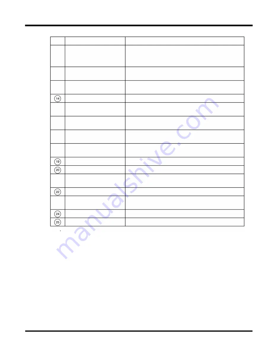
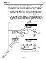
Table 1 0. 1 LCD/LE D Legend
No.
Name
Function
@
LCD
LCD indicates operation procedure, measured data and
warnings/faults.
Detailed in section 1 0.2 "LCD Display. "
@
U PS SUPPLY LED
Turned on while the inverter is on. Flashes during start-up
or stop procedure.
@
WARN I N G LED
Normally off. Turned on with warnings, flashes with AC
input abnormality.
FAU LT LED
Normally off. Turned on with faults.
@
AC I N PUT LED
Normally on with regular AC input. Flashes with AC
input under-voltage (85%) .
@
RECTI FIER LED
Turned on after DC caps are charged up through the
rectifier.
@
I NVERTER LED
Flashes during start-up or stop procedure. Turned on after
the inverter starts up, and during available.
@
AC OUTPUT LED
Turned on with AC output fed by either the bypass or
inverter sources.
BATTERY LED
Turned on with battery connected. (Aux-contact on)
FLOAT CHARG E LED
Turned on during float charge.
@
EQUALIZE CHARG E LED
Turned on during equalize charge or protection charge
with battery OH contact open.
DISCHARG E LED
Turned on during battery discharge.
@
BYPASS I N PUT LED
Normally on with regular bypass input. Flashes with bypass
under-voltage (85%) .
U PS LED
Turned on during U PS Supply.
BYPASS LED
Turned on during Bypass Supply.
- 29 -
www
. ElectricalPartManuals
. com


