3-2
3
Service Procedures
F
IGURE
3-1
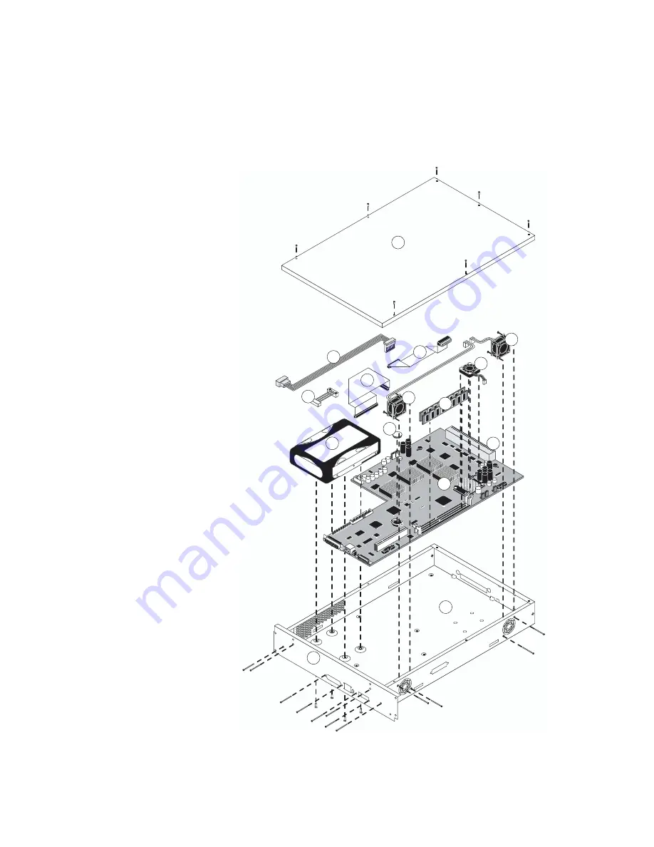
Exploded view of GA-1121 assembly
1
2
3
4
5
10
9
8
7
6
Key
1. Faceplate
2. Tray
3. GA-1121 board
4. Hard disk drive
5. HDD power cable
6. HDD cable
7. Battery
8. DIMM(s)
9. CPU assembly
10. Copier interface connector
11. Intake fan 1
12. Intake fan 2
13. Power supply cable
14. Control Panel cable
15. Top cover
11
12
13
14
15


