3-8
3
Service Procedures
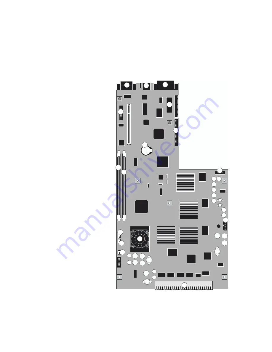
GA-1121 board
Use the procedures in this section to remove and replace the GA-1121 board for service.
F
IGURE
3-4
GA-1121 board
Key
1. 36-pin parallel port for
system software installation (J923)
2. Ethernet port (J581)
3. 25-pin parallel port
for dongle (J921)
4. Control Panel cable connector (J919)
5. BIOS socket (U202)
6. HDD cable connector (J920)
7. Battery (BT200)
8. DIMM socket (J48)
9. DIMM socket (J49)
10. HDD power cable connector (J911)
11. Power supply cable connector (J918)
12. CPU/ CPU fan/ heatsink (U1)
13. Cable connector for intake fan 1 (J353)
14. Cable connector for intake fan 2 (J352)
15. CPU fan cable connector (J351)
16. Copier interface connector
N
OTE
:
Connectors and components not
listed are not used.
1
2
3
4
5
9
8
7
6
10
11
12
13
14
15
16


