4-3
4
Preliminary on-site checkout
Checking external connections
Before removing the GA-1121 from the printer to check internal components, first
eliminate the most obvious sources of problems. Make sure that:
• The printer power cable is plugged into the wall supply and the printer is powered on.
• The GA-1121 assembly is well-seated and properly attached to the printer.
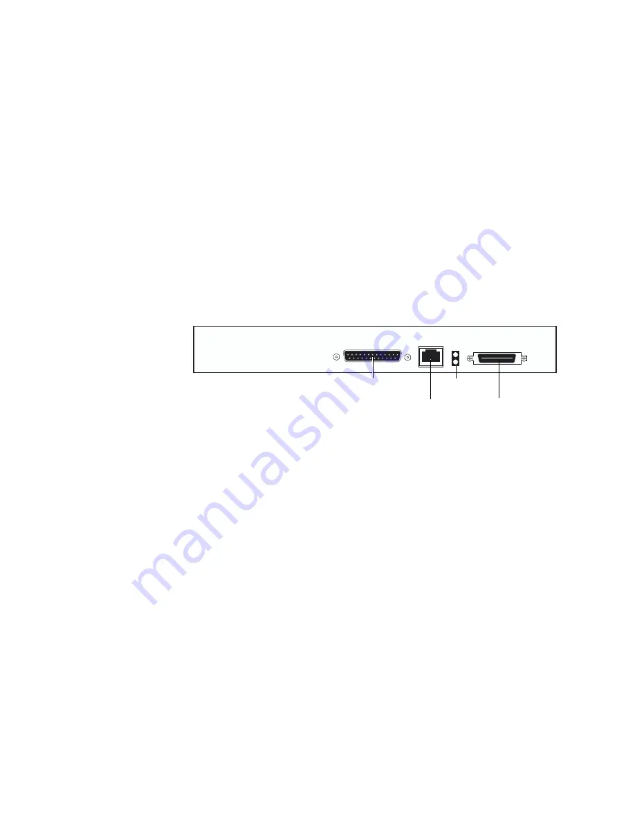
• All external cables are plugged into the proper external connectors on the GA-1121
faceplate (see Figure 4-2).
• The power cable from the GA-1121 is attached to the printer power supply.
• The top LED next to the network port is lit to indicate network connectivity.
• The Control Panel cable is attached to the GA-1121 Control Panel.
F
IGURE
4-2
External connectors on the GA-1121
If all the connections are properly in place and the power is on, proceed to the next stage
of troubleshooting.
10/100BaseT
network port
36-pin
parallel port
25-pin
parallel port
Network LEDs


