GA-1330 SETUP IN A WINDOWS ENVIRONMENT 4 - 1
[4] SETUP IN A WINDOWS ENVIRONMENT
1. Setting the IP address of the machine
A. IP address setting
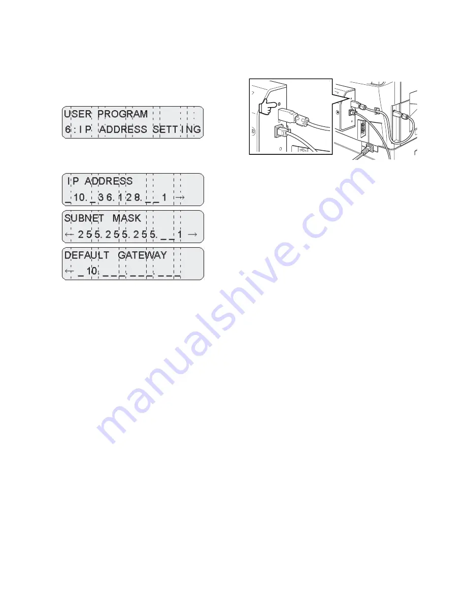
When connecting a network box, use this setting in the user program
to set the IP address of the network box.
1) With the network box connected, enter the user program from
the printer mode, and select [IP ADDRESS SETTING].
2) When [IP ADDRESS SETTING] is selected, the display indi-
cates [IP ADDRESS], [SUBNET MASK], and [DEFAULT GATE-
WAY] setting menu sequentially.
• One block is composed of 3 digits, and every menu displays 4
blocks. Use 10-key to input into each block.
• On [DEFAULT] menu, the top digit of each block is "0."
• The cursor at the right end of the selected block flashes.
• The entered value is displayed on the flashing cursor. When three
valid numbers are entered, the cursor moves to the next block on
the right. (If the number to be entered is 10, enter 10 and press
[
←
/
→
] key, or enter 010, and the cursor moves to the next block.
("0" on the top digit, in this case, is not displayed.)
• The cursor is moved by entering three digits of numbers or press-
ing [
←
/
→
] key.
• To shift between [IP ADDRESS], [SUBNET MASK], and
[DEFAULT GATEWAY], press [
←
/
→
] key.
Though, therefore, three digits are entered on the last block of [IP
ADDRESS], the display is not shifted to the first block of [SUBNET
MASK].
• When the clear key is pressed, if the value of the selected block is
changed from that on selection of setting, it is reset to the value on
selection of setting.
• When the clear key is pressed with the value unchanged or reset
to the value on selection of setting, the display is shifted to the
menu of item 1. (In this case, all the changes in values made
before pressing the clear key are cleared.)
2. Checking the IP address
To check the IP address of the machine, press the status button on
the network expansion kit to print out a network status page.
Summary of Contents for GA-1330
Page 4: ......
Page 32: ...GA 1330 ELECTRICAL SECTION 7 17 3 PARTS LAYOUT A PARTS SIDE ...
Page 33: ...GA 1330 ELECTRICAL SECTION 7 18 B SOLDER SIDE ...
Page 36: ......
Page 37: ......
Page 38: ......


