background image

October 2000  ©  TOSHIBA TEC

2 - 35

GD1080/1090

SELF-DIAGNOSIS MODE

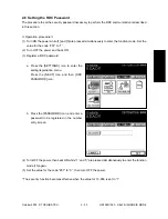
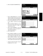
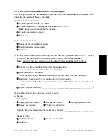
c. Press the [DESTINATION] icon, and either

select the supplier from the phone book or

enter the phone number with the digital keys.

d. Press the [CUSTOMER NO.] icon, and en-

ter the customer number with the digital

keys.

e. Press the [CONTACT NAME] icon, and en-

ter the name of the person in charge in the

character entry screen.

f. Press the [TEL NUMBER] icon, and enter

the telephone number of the person in

charge with the digital keys.

g. Press the [NEXT] icon.

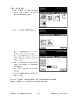
h. Press the [SHIP TO NAME] icon, and enter

the name of the person who will receive the

toner cartridges in the letter entry screen.

i. Press the [SHIP TO ADR] icon, and enter

the address to where the toner cartridges

are to be delivered in the letter entry screen.

j. Check the entered information, then press

the [SET] icon if it is correct.

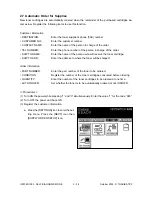
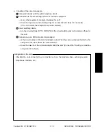
b. Press the [OTHER INFORMATION] icon.

Summary of Contents for GD 1080

Page 1: ... the Bookmarks to open the Contents and display Bookmarks created for the document Click a bookmark s name to go to the Page marked by that bookmark Click the Thumbnails to open the overview area and display thumbnail images of each document page Click a thumbnail to go to the Page marked by that thumbnail Copyright TOSHIBA TEC CORPORATION 2001 ALL RIGHTS RESERVED ...

Page 2: ...cally be sure to turn the main switch off and unplug the power cord during service Be sure not to touch high temperature sections such as the exposure lamp the fuser unit the damp heater and their periphery Be sure not to touch high voltage sections such as the chargers high voltage transformer IH control circuit exposure lamp control inverter inverter for the LCD backlight and power supply unit E...

Page 3: ...noted in this manual or other related documents Be careful not to reassemble small parts such as screws washers pins E rings star washers in the wrong places 7 Basically the machine should not be operated with any parts removed or disassembled 8 Precautions Against Static Electricity The PC board must be stored in an anti electrostatic bag and handled carefully using a wristband because the ICs on...

Page 4: ...1 ERROR CODES 2 SELF DIAGNOSIS MODE 3 TROUBLESHOOTING 4 PRECAUTIONS FOR INSTALLATION OF FAX UNIT 5 UPDATING THE FIRMWARE ...

Page 5: ... Mode 13 2 7 2 5 Fax Clearing Mode 1 2 30 2 6 Setting the RDC Password 2 33 2 7 Automatic Order for Supplies 2 34 3 TROUBLESHOOTING 3 1 3 1 Flow Chart for RecommendedTelephone Screening 3 2 3 2 Error Analysis Flow 3 5 3 3 Lists Required When Problem Has Occurred in the Field 3 6 3 4 Other Information Required for Error Analysis 3 11 4 PRECAUTIONS FOR INSTALLATION OF FAX UNIT 4 1 4 1 Installation o...

Page 6: ...wn below The error code list and status code list are available in the following pages The reception journal is output in the same form TRANSMISSION JOURNAL TIME MM DD YY TIME TEL NO 1 XXXXXXXXX TEL NO 2 XXXXXXXXX NAME X X X X X X X NO FILE NO DATE TIME DURATION PGS TO DEPT MODE STATUS 001 001 12 01 09 00 00 55 2 ABCD G3 xxx OK xx Status code Error code ...

Page 7: ...F DIS cannot be detected Check the receiver and attempt the transmission again DIS NSF that cannot be handled by the sender was received The receiver re ceived NSS DCS other than those declared by DIS NSF Check the transmis sion reception functions and attempt the communication again DCN was received in the phase B DCS DTC cannot be detected The sender performed fall back but the transmission was ...

Page 8: ...e Transmission speed Resolution Encoding system 0 2400 8 x 3 85 MH 1 4800 8 x 7 7 MR 2 7200 8 x 15 4 MMR 3 9600 JBIG 4 12000 16 x 15 4 5 14400 6 16800 7 19200 8 21600 300 x 300 9 24000 A 26400 B 28800 C 31200 D 33600 E F Error code Content Situation and corrective action E8 F0 F1 HDD error Software trouble Hardware noise Hardware is defective Software is defective Hardware is defective ...

Page 9: ...ut Post message not detected Poor image quality Image memory error Software overdrive Hardware noise Symptom Communication was interrupted be cause the memory became full Redialing was attempted for the specified number of times but the line is still busy DIS is not detected Received DIS unable to be handled Received DCS which is beyond the capability of the receiver Fall back is not made successf...

Page 10: ...nish the self diagnosis mode turn the power OFF and then back ON Do not cancel the mode using the keys 0 and 9 A malfunction may be caused because the start up process is not per formed properly Keys to be pressed to enter each mode 0 3 POWER 0 5 POWER 0 8 POWER 1 3 POWER 1 POWER Digital keys on the list output screen Do not enter the self diagnostic mode Function Output check modem test dialing t...

Page 11: ...CML test output are performed in the test mode 03 1 Modem test CML test Operation procedure 0 3 FAX FAX Digital key START Operation started POWER OFF POWER Switch line 1 and 2 Code End 2 Dialing test Operation procedure 0 3 FAX FAX Digital key START Digital key POWER Switch line 1 and 2 Code START START POWER OFF End C S C S ...

Page 12: ...em test 462 Hz Modem test 1300 Hz Modem test 33 6 kbps V 34 Modem test 28 8 kbps V 34 Modem test 24 0 kbps V 34 Modem test 16 8 kbps V 34 Dialing test 10PPS Tested with the digital keys The dial number corresponding to the key which was pressed is kept outputting on the circuit The pressed key is displayed on the control panel Dialing test PB Tested with the digital keys The dial number correspond...

Page 13: ... processing is performed in the adjustment mode 05 1 Setting parameters for the fax image processing Operation procedure SET 0 5 Digital key START Digital key or POWER OFF POWER Code FC key INTERRUPT Input adjustment value Save the value in the RAM CANCEL C S In case the value is corrected can be entered with the FC key ...

Page 14: ...ustment Error diffusion Center value Manual density fine adjustment Error diffusion Lighter step value Manual density fine adjustment Error diffusion Lighter step value Manual density fine adjustment Error diffusion Darker step value Manual density fine adjustment Error diffusion Darker step value Auto density fine adjustment Error diffusion Auto density fine adjustment Error diffusion Mode Fax Fa...

Page 15: ...F Save the value in the RAM C S In case the value is corrected Code 701 Element Fax Adjustment item Destination 1 Asia 2 Australia 3 Hong Kong 4 U S A 5 Germany 6 Great Britain 7 Italy 8 Belgium 9 Holland 10 Finland 11 Spain 12 Austria 13 Switzerland 14 Sweden 15 Denmark 16 Norway 17 Portugal 18 France 19 Greece 20 Poland 21 Hungary 22 Czech Rep 23 Turkey 24 South Africa Mode Fax Image mode ALL De...

Page 16: ...ERRUPT Set value cannot be changed 2 4 Function Mode 13 Various functions are set in the function mode 13 1 Procedure to set the functions Enter a code using the digital keys and change the set value Operation procedure CANCEL SET 1 3 Digital key START Digital key or POWER POWER Code Enter a value INTERRUPT OFF Save the value in the RAM C S In case the value is corrected ...

Page 17: ...edialing is not per formed and it is determined that the transmission is terminated due to error 0 300 600Hz 1 300 650Hz 2 390 550Hz 3 400 450Hz 4 350 480Hz 5 300 500Hz 6 Reserved 7 Reserved 0 2sec 1 800ms 2 400ms 3 1sec 4 1 3sec 5 1 8sec 6 2 5sec 7 500ms 0 OFF 1 50ms 2 100ms 3 200ms 0 OFF 1 70ms 2 160ms 3 240ms 0 BZT DTC LCC 1 LCC 5sec 2 DTC only 3 FRN DTC LCC 4 DTC JPN 5 NO DTC LCC 0 20sec 1 10s...

Page 18: ... is interrupted because any of the settings for DTC LCC is not satisfied during redialing that redialing is ignored since it is con sidered as an internal retry Set the number of redialings Set the time for a pause when it is inserted between the dial numbers Set the interval between digits for DP dialing Set the interval between redialings Set the make break ratio for DP dialing Set the ON OFF ti...

Page 19: ... dialing the second international dial ac cess code Sets the international access code Setting for the receiver attenuator Sets time that a busy tone signal is output to be determined it is ON Sets time that a busy tone signal is not output to be determined it is OFF Set the difference between the high output and low output of the MF signal Setting for intermittent DTC func tion Select the exchang...

Page 20: ...C JPN USA 5 NO DTC LCC 0 20sec 1 10sec 2 8sec 3 15sec 4 3 3sec 0 300 600Hz 1 300 650Hz 2 390 550Hz 3 400 450Hz 4 350 480Hz 5 300 500Hz 6 Reserved 7 Reserved 0 2sec 1 800ms 2 400ms 3 1sec 4 1 3sec 5 1 8sec 6 2 5sec 7 150ms 0 OFF 1 50ms 2 100ms 3 200ms 0 OFF 1 70ms 2 160ms 3 240ms 0 BZT DTC LCC 1 LCC 5sec 2 DTC only 3 FRN LCC DTC 4 DTC JPN USA 5 NO DTC LCC 0 20sec 1 10sec 2 8sec 3 15sec 4 3 3sec 0 N...

Page 21: ...ecreased one by one 00 No detection 01 300Hz 600Hz 02 300Hz 650Hz 03 390Hz 550Hz 04 400Hz 450Hz 05 350Hz 480Hz 06 300Hz 500Hz 07 France Dual Tone not used 10 No detection 11 300Hz 600Hz 12 300Hz 650Hz 13 390Hz 550Hz 14 400Hz 450Hz 15 350Hz 480Hz 16 300Hz 500Hz 17 France Dual Tone not used Numeric value of 3 digits Default setting 4 digits 0 OFF 1 3dB 0 80 650ms 1 450 550ms 2 200 650ms 3 400 600ms ...

Page 22: ...large value Set if a delay 500ms is inserted before sending the V 21 signal and timing is shifted to avoid the line echo Set the initial modem speed to be declared by DIS DCS Select the line to monitor CI ON satiable time CI OFF satiable time Select either one of the followings to declare the maximum recording width to the other party when the specified paper size is not available the largest pape...

Page 23: ...e output conditions Set whether the multi address transmission report is printed or not Also select the output condi tion Set whether the multi polling trans mission report is printed or not Also select the output condition Set whether the relay multi address transmission report is printed or not Also select the output condi tion Set whether the relay multi address reception report is printed or n...

Page 24: ... transmission level for communica tion other thanV 34 The smaller the value the higher the transmission level becomes If errors occur fre quently or training is not sent the transmission level should be changed Set the equalizer value which has frequency characteristics For the long distance communication it is recommended to set a large value Set how the communication is con trolled when the 4th ...

Page 25: ... Line 1 Fall back condition for transmitter No of PPR reception V 34 Line 1 Fall back condition for receiver No of PPR reception V 34 Line 1 TX attenuation value V 34 Line 1 Initial modem speed for V 34 communication SUB SEP PWD functions Coding capability commu nication capability Reception end tone timing V 34 symbol rate Line 1 V 34 fall back method Line 1 Recovery transmission Protocol type Ba...

Page 26: ... in the V 34 communication Maximum modem speeds for each setting are as follows 2400 21600bps 2800 26400bps 3000 28800bps 3200 31200bps 3492 33600bps Set the number of steps in which the modem speed is fall backed Set the modem transmission at tenuation level for the V 34 commu nication The smaller the set value the higher the transmission level becomes If errors occur frequently or training is no...

Page 27: ...ct the NCU termination circuit Set if the security function for RDC is used Enter an error decimal code of the error which needs to be reported on the protocol trace list Error 0 when performing the set ting operation for the automatic or der Return it to 1 when the set ting is finished Enter this value when making an automatic order Sets the differen tial value for the total counter to judge the ...

Page 28: ... 1 User registration area NVRAM 1 ID registration area 2 Phone book registration area 3 Group registration area 4 Program registration area 2 Image data area HDD NVRAM 1 Transmission file 2 Reception file 3 Image data file management area 3 System setting area NVRAM 1 Settings in the function mode 13 Areas 100 999 2 Home position 3 Journal area 4 Error count area ...

Page 29: ...red 3 System setting area NVRAM Values are reset to the default settings 3 Clearing the image data area 1 User registration area NVRAM Not initialized 2 Image data area HDD NVRAM Initialized so that there are no data stored 3 System setting area NVRAM Not initialized 4 Clearing the system setting area 1 User registration area NVRAM Not initialized 2 Image data area HDD NVRAM Not initialized 3 Syst...

Page 30: ...Setting Mode 08 described in the chapter 2 3 If the initialization is performed with the wrong destination setting the default value of the function mode is changed to that for the wrong destination Contents Clearing all Clearing the non user area Clearing the image data area Clearing the system setting area Mode Fax Fax Fax Fax Operation procedure 1 Digital key START INITIALIZE POWER OFF POWER Co...

Page 31: ...r the code 957 to 1 2 Turn OFF the power and back ON 3 Register a RDC password 4 Turn OFF the power then back ON while 1 and 3 are pressed simultaneously to enter the function mode 13 again 5 Set the value for the code 957 to 0 then turn OFF the power The security function becomes effective when the value for 13 956 is set to 1 b Press the PASSWORD icon and enter a password to be registered in the...

Page 32: ... Enter the name of the person who will receive the toner cartridge SHIP TO ADR Enter the address to where the toner will be shipped Order information PART NUMBER Enter the part number of the toner to be ordered CONDITION Register the number of the toner cartridges consumed before ordering QUANTITY Enter the number of the toner cartridges to be ordered at one time AUTO ORDER Set whether the toner i...

Page 33: ...son in charge in the character entry screen f Press the TEL NUMBER icon and enter the telephone number of the person in charge with the digital keys g Press the NEXT icon h Press the SHIP TO NAME icon and enter the name of the person who will receive the toner cartridges in the letter entry screen i Press the SHIP TO ADR icon and enter the address to where the toner cartridges are to be delivered ...

Page 34: ...nd enter the number of the cartridges to be ordered with the digital keys f Press ON or OFF icon for the AUTO ORDER g Check the settings and press SET icon if they are correct 4 Make an toner order a Press the SET icon to enter the setting menu Press the NEXT icon then the SUPPLY ORDER SETUP icon b Press the TONER ORDERING icon 5 Turn OFF the power then back ON while 1 and 3 simultaneously are pre...

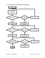
Page 35: ...cian does not need to be despatched 3 TROUBLESHOOTING Call from customer Telephone screening Not solved Not solved Dispatch a service technician Field service Trouble solved Assistance by phone for the field service technician from the remote diagnosis center Field service ...

Page 36: ...splayed on the LCD Is the AC power cable properly plugged in Plug it in properly Dispatch a service technician Set the recording paper Is a communication journal printed out Is the recording paper set correctly Set it correctly Set an document Dispatch a service technician Is the document set correctly Set it correctly Dispatch a service technician Is the image which was not sent successfully prin...

Page 37: ...e copied image Using specified recording paper Use the specified recording paper Dispatch a service technician Any problem with the auto dialing function Is COMMUNICATION ERROR displayed on the LCD Is the dial type correct Dispatch a service technician Select the correct dial type DP PB in the function setting mode Connect the applicable connector Correct the phone number Dispatch a service techni...

Page 38: ... receiving side using a G3 machine Check the error code and dispatch a service technician Any problem with the reception Is the automatic reception possible in the auto reception mode Is the manual reception possible in the manual reception mode Is the received document normal Check noise on the telephone circuit or any defect of the other equipment Perform the communication Interference test Disp...

Page 39: ...r information and function list for maintenance Confirm that no received document data are stored in the memory by checking the Memory RX LED and reservation list Turn OFF the power and check the following items before starting the diagnosis Is the power cable properly plugged in Are all the connectors securely connected Notes Before replacing the parts confirm that there is no data to be transmit...

Page 40: ...ine to stop the communication when trouble occurs Since the only last communication is reported on the protocol trace list if the telephone line is not discon nected immediately after the trouble has occurred next communication might come in before the line is disconnected and be printed out instead of the communication in question Do not turn OFF the power before printing the protocol trace list ...

Page 41: ... for address and size vary depend on the type of trouble All lists protocol trace lists for 2 lines error count lists for 2 lines function list and memory dump list for system and board Supply order form 3 1 1 n START 3 1 2 n START 3 2 1 n START 3 2 2 n START 3 3 n START 3 4 n 1 5 8 0 1 3 5 0 n 2 0 0 0 n START 3 5 n Address 8 digits n Size 4 digits n START 3 7 n 1 5 8 0 1 3 5 0 n 2 0 0 0 n START 3...

Page 42: ...0xB0080010 3031323334353637 38393A3B3C3D3E3F 0123456789ABCDEF PROTOCOL TRACE LIST LINE 1 ROM VER TIME 11 13 00 09 00 TEL NO 1 TEL NO 2 NAME TIME S R FCF DATA FIF DATA ASCII 0035 R NSF 00000912096d303030FF m0000 0035 R CSI 38312020202020202020 81 0035 R DIS 00000000 01110011 10010111 00100000 2 Memory dump list System Command status information between the CPU controlled by the fax board and the CP...

Page 43: ... Frequency of the occurrence of a particular error can be checked ERROR COUNT LIST LINE 1 ROM VER TIME 11 13 00 09 00 TEL NO 1 TEL NO 2 NAME TRANSMISSION STATUS HISTORY ACTUAL 11 03 00 12 00 11 10 00 12 15 11 10 00 12 16 00 980 1000 95 50 33 0 1000 0 50 99 5 1000 2 50 FUNCTION LIST FOR MAINTENANCE ROM VER TIME 11 13 00 09 00 TEL NO 1 TEL NO 2 NAME CODE NO DATA CODE NO DATA CODE NO DATA CODE NO DAT...

Page 44: ...ty s line of the other side is busy talking If this error occurs frequently it can be decreased somewhat by increasing the number of redialing attempts Also it can be checked if the communication fails with a particular address 8 Reception journal Reception records for 40 communications are listed Occurrence conditions of the communication errors can be checked with the information such as the tim...

Page 45: ...with the tone from the speaker Note Turn OFF the circuit monitoring function after the checking is finished 13 338 0 Signals from the transmitter and that from the receiver clash n Check the model name of the other party s machine Noise occurring on the circuit n Ask the telephone or telecommunications company if the line condition is normal Busy tone is heard from the other party during the commu...

Page 46: ...ccur since the line condition differs depending on each communication If the same errors occur to the image which was resent they can be decreased by reducing the transmission speed of the sending side Communication cannot be made with a particular number Information of the other side s machine If the communication is impossible with a particular number it is considered that the other party s mach...

Page 47: ...t be started Circuit switching device n Are the circuit settings DP10 DP20 PB of the circuit switching device the same as those for this unit Connection via an ISDN circuit terminal adaptor n Is the circuit number of the terminal adaptor correct Is it the same number as that for the fax assigned to the other device ex data modem n Does the noise from the terminal adaptor affect the line Connect th...

Page 48: ...GD1080 1090 TROUBLESHOOTING 3 14 October 2000 TOSHIBA TEC f Settings of the automatic energy saving and automatic power off Auto clearing 08 204 Automatic energy saving 08 205 Automatic power OFF 08 206 ...

Page 49: ...gion in 08 201 and 701 1 POWER n 100 n START It takes about 20 seconds for the digital keys to be operable after the power is turned ON It takes about 10 seconds until the display changes from 100 to CL About FAX clearing mode Clearing all When Clearing all is performed the following operations are performed Data in the phone book ID registration transmission reception journal memory transmission ...

Page 50: ...on code is set changed Setting the country region code 1 Turn ON the power while pressing 0 and 8 simultaneously 2 Enter 701 with the digital keys and press START 3 Enter a code with the digital keys and they press the SET icon or the INTERRUPT key 2 3 Setting mode 08 Country Region Code AS 1 AU 2 HK 3 US 4 DE 5 GB 6 IT 7 BE 8 NL 9 FI 10 ES 11 AT 12 CH 13 SE 14 DK 15 NO 16 PT 17 FR 18 GR 19 PL 20 ...

Page 51: ...e NCU board These country region require code setting on the NCU using the FG harness All other countries regions have only W1 connection on the board Fig 4 2 1 FG harness DE GB NL IT AT BE CH SE DK NO FI PT FR ES GR IE ZA SG HK AU NZ W2 W2 W2 W1 W2 W2 W2 W2 W1 W2 W1 W2 W2 W2 W2 W2 W2 W2 W2 W2 W2 FRAME ...

Page 52: ...reservation list to confirm that there is no reception data F code data and memory transmission data respectively since there is possibility that data can be lost when the power is turned OFF 3 Update the firmware following the Procedure in the next page 4 Be sure to erase data in the memory by performing the Fax clearing mode Clearing the image data area before performing any operation after the ...

Page 53: ...nnector of the fax control board FAX board 4 Turn ON the power while pressing 0 and 8 simultaneously The downloading is automatically started 5 Turn OFF the power when the LED on the download board starts to flash Disconnect the download board 6 Output the protocol trace list and check the version of the ROM 2 Take off the option cover of the copier Re move one screw and take off the connector cov...

Reviews: