background image

GD-1210/1250/1270/1160/1260

© 2006 - 2011 TOSHIBA TEC CORPORATION All rights reserved

DIALING/COMMUNICATION CONTROL

3 - 12

(4) Training

The training is performed in the binary procedure to surely transmit the image signals.

• Training signal

The training signal is transmitted following the DCS signal at the modem speed specified by 
the DCS signal. Responding to this training signal, the receiving side adjusts the auto-equal-
izer.

• Format of the training signal

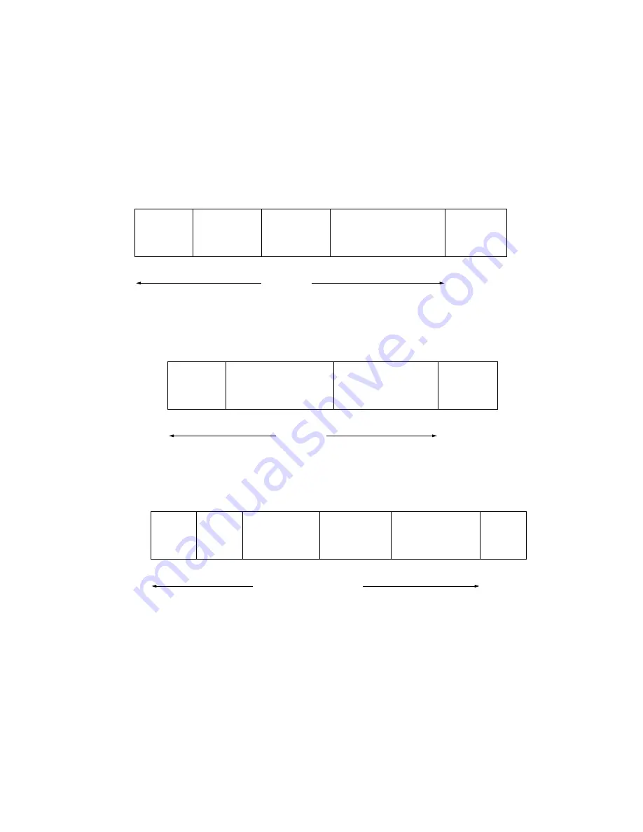
- 14.4 Kbps, 12 Kbps

 Fig. 3-4

- 9600 bps, 7200 bps

 Fig. 3-5

- 4800 bps, 2400 bps

 Fig. 3-6

• TCF signal

An error may occur in the image data if the training is not performed correctly. The transmit-
ting side sends a TCF signal and checks if any error occurs in image data before the image 
data communication to follow. When the receiving side detects an error in the TCF signal, it 
transmits an FTT signal to the transmitting side to request the retraining. When there is no 
error, the receiving side transmits a CFR signal.
The TCF signal transmits all zeros for 1.5 seconds at the same modem speed as that for the 
training signal.

Alternation

of ABAB

Scrambled binary data “1”

Segment 1

Segment 2

Segment 3

Segment 4

106 msec

1240 msec

27 msec

20 msec

1393 msec

Equalizer

adjustment

pattern

Chain-store

information

sequence

TCF

(Binary)

(Hexa or octal)

V.29

No signal

TCF

Repeating 2-state

signal

Scrambled data “1”

Segment 1

Segment 2 / Segment 3

Segment 4

20 msec

53 msec+160 msec

20 msec

253 msec

Non-

modulated

carrier

No signal

(Binary)

Scrambled data “1”

(Hexa or octal)

0° to 180°

2-phase pattern

(Binary)

TCF

Continuous
180° phase

inversion

Segment 1Segment 2

Segment 3

Segment 4

4,800 bps: 923 msec,

2,400 bps: 1158 msec

V.27ter

Segment 5

Summary of Contents for GD-1250

Page 1: ...SERVICE MANUAL FACSIMILE GD 1210 1250 1270 1160 1260 File No SME060009D0 R060121A4400 TTEC Ver04_2011 12 ...

Page 2: ...alk Macintosh and Mac are trademarks of Apple Computer Inc in the U S and other countries PostScript is a trademark of Adobe Systems Incorporated NOVELL NetWare and NDS are trademarks or registered trademarks of Novell Inc Molykote is a registered trademark of Dow Corning Corporation Other company names and product names in this manual are the trademarks of their respective companies 2006 2011 TOS...

Page 3: ...ipment is quite heavy and e STUDIO206L 256 306 weighs approximately 58 kg 127 87 lb and e STUDIO356 456 weighs approximately 61 kg 134 48 lb therefore pay full attention when handling it When transporting installing the equipment employ four persons and be sure to move it by the casters while lifting the stoppers The equipment is quite heavy and weighs approximately 245 kg 540 12 lb therefore pay ...

Page 4: ...high temperature sections such as the exposure lamp fuser unit damp heater and areas around them Be sure not to touch high voltage sections such as the chargers transfer belt 2nd transfer roller developer high voltage transformer exposure lamp control inverter inverter for the LCD back light and power supply unit Especially the board of these components should not be touched since the electric cha...

Page 5: ...ed batter ies and IC RAMs including lithium batteries follow the relevant local regulations or rules 6 When the option has been installed When the EFI printer board has been installed be sure to unplug the power cable before performing maintenance and inspection otherwise troubles such as a communication error may occur Caution Dispose of used batteries and IC RAMs including lithium batteries acco...

Page 6: ......

Page 7: ...355 455 e STUDIO206L 256 306 356 456 1 22 1 7 5 e STUDIO555 655 755 855 e STUDIO556 656 756 856 1 23 1 8 Layout of PC Boards 1 24 2 LSU RELATED FUNCTIONS 2 1 2 1 Recording Mode 2 1 2 2 Recording Paper Selection Algorithm and Printing Algorithm 2 2 2 2 1 Recording paper selection algorithm 2 2 2 2 2 Printing algorithm 2 2 2 2 3 Setting for the split recording 2 6 2 3 Recording Paper and Function 2 ...

Page 8: ...tion of Circuits 4 3 4 2 1 Configuration 4 3 4 2 2 Line path switching control circuit 4 5 4 2 3 Dial pulse generation circuit 4 7 4 2 4 Line current detection circuit 4 9 4 2 5 CI detection circuit 4 11 4 2 6 Line monitor circuit 4 13 4 3 PC Boards 4 16 5 INSTALLATION 5 1 5 1 Explanation to the Users 5 1 ...

Page 9: ...AX functions P 1 8 1 5 Options Be sure to use the FAX unit and the 2nd line for the FAX unit only in the following combinations Models FAX unit 2nd line for FAX unit e STUDIO2500c 3500c 3510c GD 1210 GD 1160 e STUDIO2330C 2820C 2830C 3520C 3530C 4520C e STUDIO2040C 2540C 3040C 3540C 4540C GD 1250 GD 1260 e STUDIO5520C 6520C 6530C e STUDIO5540C 6540C 6550C GD 1270 GD 1260 e STUDIO205L 255 305 355 4...

Page 10: ...lines mm Vertical direction 15 4 lines mm 7 7 lines mm 3 85 lines mm 16 lines mm 8 lines mm Combination U Fine 16 x 15 4 lines mm 15 4 x 16 lines mm Semi U Fine 8 x 15 4 lines mm 15 4 x 8 lines mm Fine 8 x 7 7 lines mm 7 7 x 8 lines mm Normal 8 x 3 85 lines mm 3 85 x 8 lines mm Effective scanning area Fig 1 1 mm Note Note Operation from the panel is automatically converted at the receiving capabil...

Page 11: ...dBm or lower cannot be detected Specifications of the communication mode LG 355 6 350 1 LD 431 8 426 3 High speed mode Toshiba original procedure mode G3 mode ECM Horizontal scanning den sity 8 dots mm 300 dpi Reception only 16 dots mm Same as on the left Same as on the left Vertical scanning density 3 85 lines mm 7 7 lines mm 300 dpi Reception only 15 4 lines mm Same as on the left Same as on the...

Page 12: ...mm 24 lines mm with the smoothing processing Recording paper size and the effective printing area Unit mm inch Paper size Dimension width x length Printing area A5 R 148 x 210 143 x 204 5 B5 R 182 x 257 177 x 251 5 B5 257 x 182 252 x 176 5 A4 R 210 x 297 205 x 291 5 A4 297 x 210 292 x 204 5 B4 257 x 364 252 x 358 5 A3 297 x 420 292 x 414 5 FOLIO 210 x 330 205 x 324 5 ST R 139 7 x 216 5 5 x 8 5 134...

Page 13: ...he followings are possible Memory input during the memory transmission Memory input during the memory reception Copying during the memory transmission Reception during the copying Reception during the memory output Reception during the list output Laser printing on plain paper Printing is made on the standard size paper A3 LD B4 COMP A4 LT LG A4 R LT R B5 B5 R FOLIO and A5 R ST R with the laser sy...

Page 14: ...Delayed dialing Documents are transmitted automatically to the preset number at the preset time Redialing When the receiving side is busy during the automatic dialing the machine keeps dialing at a fixed interval for a specified number of times Receiving tone completion tone Sound notifies that the reception of a FAX document or printing of a received document has been completed List output The fo...

Page 15: ...rator s manual for facsimile function 1 pc 1 pc 1 pc Modular cord 2 m 1 pc 1 pc 1 pc Unpacking instruction 1 set 1 set 1 set Parts GD 1210 GD 1250 GD 1270 Fax unit 1 pc 1 pc 1 pc SG3 label 1 pc 1 pc 1 pc FCC Part 68 label U S A IC label Canada NA only 1 pc 1 pc 1 pc DTS label EU EU only 1 pc 1 pc 1 pc Teleprompt label New Zealand AU only 1 pc 1 pc 1 pc Notice to users label New Zealand AU only 1 p...

Page 16: ...260 GD 1260 Option Function e STUDIO205L 255 305 355 455 e STUDIO555 655 755 855 Reversing Automatic Document Feeder RADF Feeds originals MR 3021 3022 Finisher Sorts out docu ments to be output for the FAX copy ing operation MJ 1101 MJ 1031 MJ 1024 MJ 1025 MJ 5004 MJ 5005 MJ 5006 MJ 1027 MJ 1028 MJ 1029 2nd line for FAX unit Adds one extra communication line GD 1260 GD 1260 Option Function e STUDI...

Page 17: ... 1 9 1 Option Function e STUDIO206L 256 306 356 456 Reversing Automatic Document Feeder RADF Feeds originals MR 3021 3022 Finisher Sorts out docu ments to be output for the FAX copy ing operation MJ 1101 MJ 1106 MJ 1032 MJ 1033 MJ 5004 MJ 5005 MJ 5006 2nd line for FAX unit Adds one extra communication line GD 1260 11 12 ...

Page 18: ... 1 6 1 e STUDIO2500c 3500c 3510c Fig 1 2 FAX unit GD 1210NA AU AS EU C TW KR 2nd Line for FAX unit GD 1160 NA EU N C TW Bridge Kit KN 3500 Finisher MJ 1101 Drawer Module MY 1031 C Large Capacity Feeder LCF KD 1019 A4 LT C Paper Feed Pedestal PFP KD 1018 C Saddle stitch finisher MJ 1030 Reversing Automatic Document Feeder RADF MR 3018 08 04 ...

Page 19: ...2830C 3520C 3530C 4520C Fig 1 3 Bridge Kit KN 4520 Saddle stitch finisher MJ 1030 Hanging finisher MJ 1031 Finisher MJ 1101 Drawer Module MY 1032 C Large Capacity Feeder LCF KD 1024 A4 LT C Paper Feed Pedestal PFP KD 1023 C FAX unit GD 1250NA AU AS EU C TW 2nd Line for FAX unit GD 1260 NA AU EU C TW Reversing Automatic Document Feeder RADF MR 3018 08 04 ...

Page 20: ...TEC CORPORATION All rights reserved SPECIFICATIONS AND OUTLINE OF SYSTEM 1 12 1 6 3 e STUDIO5520C 6520C 6530C Fig 1 4 Saddle stitch finisher MJ 1104 Finisher MJ 1103 FAX unit GD 1270NA AU AS EU C TW 2nd Line for FAX unit GD 1260 NA AU EU C TW 09 05 ...

Page 21: ... Saddle stitch Finisher MJ 1024 Finisher MJ 1101 Drawer Module MY 1033 Large Capacity Feeder LCF KD 1026 Paper Feed Pedestal PFP KD 1025 Reversing Automatic Document Feeder RADF MR 3022 Finisher Hanging type MJ 1031 Job Separator MJ 5006 Job Separator MJ 5004 Saddle stitch Finisher MJ 1025 e STUDIO355 455 e STUDIO205L 255 305 e STUDIO355 455 e STUDIO205L 255 355 e STUDIO355 455 e STUDIO205L 255 35...

Page 22: ...TEC CORPORATION All rights reserved SPECIFICATIONS AND OUTLINE OF SYSTEM 1 14 1 6 5 e STUDIO555 655 755 855 Fig 1 6 Saddle stitch finisher MJ 1028 1029 Finisher MJ 1027 FAX unit GD 1250NA EU AU AS C 2nd Line for FAX unit GD 1260 NA EU N AU C 09 05 ...

Page 23: ... Document Feeder RADF MR 3022 e STUDIO3540C 4540C e STUDIO2040C 2540C 3040C Reversing Automatic Document Feeder RADF MR 3021 Bridge Kit KN 4530 Saddle stitch finisher MJ 1106 Hanging finisher MJ 1031 Finisher MJ 1101 Drawer Module MY 1035 C Large Capacity Feeder LCF KD 1028 A4 LT C Paper Feed Pedestal PFP KD 1027 C FAX unit GD 1250NA AU AS EU C TW 2nd Line for FAX unit GD 1260 NA AU EU C TW 11 04 ...

Page 24: ...TEC CORPORATION All rights reserved SPECIFICATIONS AND OUTLINE OF SYSTEM 1 16 1 6 7 e STUDIO5540C 6540C 6550C Fig 1 8 Saddle stitch finisher MJ 1104 Finisher MJ 1103 FAX unit GD 1270NA AU AS EU C TW 2nd Line for FAX unit GD 1260 NA AU EU C TW 11 04 ...

Page 25: ...eserved GD 1210 1250 1270 1160 1260 SPECIFICATIONS AND OUTLINE OF SYSTEM 1 17 1 1 6 8 e STUDIO556 656 756 856 Fig 1 9 Saddle stitch finisher MJ 1028 1029 Finisher MJ 1027 FAX unit GD 1250NA EU AU AS C 2nd Line for FAX unit GD 1260 NA EU N AU C 11 12 ...

Page 26: ... FAX Unit GD 1250 2nd Line for FAX Unit GD 1260 Bridge Kit KN 2520 Finisher MJ 1101 Drawer Module MY 1033 Large Capacity Feeder LCF KD 1026 Paper Feed Pedestal PFP KD 1025 Reversing Automatic Document Feeder RADF MR 3022 Job Separator MJ 5006 Job Separator MJ 5004 e STUDIO356 456 e STUDIO356 456 e STUDIO206L 256 356 e STUDIO356 456 e STUDIO206L 256 356 Reversing Automatic Document Feeder RADF MR 3...

Page 27: ...70 1160 1260 SPECIFICATIONS AND OUTLINE OF SYSTEM 1 19 1 1 7 Overview 1 7 1 e STUDIO2500c 3500c 3510c Fig 1 11 Fig 1 12 Drawers Paper feed pedestal or Large capacity feeder Reversing automatic document feeder Power switch LINE connector TEL connector LINE2 connector 09 05 ...

Page 28: ...ATIONS AND OUTLINE OF SYSTEM 1 20 1 7 2 e STUDIO2330C 2820C 2830C 3520C 3530C 4520C e STUDIO2040C 2540C 3040C 3540C 4540C Fig 1 13 Fig 1 14 Reversing automatic document feeder Power switch LINE connector TEL connector LINE2 connector Drawers Paper feed pedestal or Large capacity feeder 11 04 ...

Page 29: ...d GD 1210 1250 1270 1160 1260 SPECIFICATIONS AND OUTLINE OF SYSTEM 1 21 1 1 7 3 e STUDIO5520C 6520C 6530C e STUDIO5540C 6540C 6550C Fig 1 15 Fig 1 16 Power switch LINE connector TEL connector LINE2 connector Drawers Drawers or Large capacity feeder 11 04 ...

Page 30: ...011 TOSHIBA TEC CORPORATION All rights reserved SPECIFICATIONS AND OUTLINE OF SYSTEM 1 22 1 7 4 e STUDIO205L 255 305 355 455 e STUDIO206L 256 306 356 456 Fig 1 17 Fig 1 18 LINE2 connector LINE connector TEL connector Power switch 11 12 ...

Page 31: ...TION All rights reserved GD 1210 1250 1270 1160 1260 SPECIFICATIONS AND OUTLINE OF SYSTEM 1 23 1 1 7 5 e STUDIO555 655 755 855 e STUDIO556 656 756 856 Fig 1 19 Fig 1 20 TEL connector LINE connector LINE2 connector Power switch 11 12 ...

Page 32: ...rd Control the line of telephone for 1st line NCU2 NCU2 board Control the line of telephone for 2nd line FAX PWR FAX power board Supplies the power 12V 24V of FAX NCU e STUDIO2500c 3500c 3510c e STUDIO2330C 2820C 2830C 3520C 3530C 4520C e STUDIO2040C 2540C 3040C 3540C 4540C e STUDIO5520C 6520C 6530C e STUDIO5540C 6540C 6550C e STUDIO555 655 755 855 e STUDIO556 656 756 856 e STUDIO205L 255 305 355 ...

Page 33: ...2 1 Recording Mode This machine offers various printing modes such as the selection of the applicable recording paper and the recording method etc to meet users needs To take full advantage of these features it is important to understand the concepts of the recording paper selection algorithm and printing algorithm as described in 2 2 ...

Page 34: ...t printing 2 2 1 Recording paper selection algorithm It is possible to distinguish the size of each received image A3 LD B4 LG A4 LT B5 A5 Basically recording paper of the same size as the original is used for printing If recording paper of the size is not available this algorithm selects paper of another size according to the setting in the Setting Mode 1 Actual Size Mode 13 517 0 Printing is per...

Page 35: ...e note below Discard printing function ON Blank space within the discard parameter Discard printing actual size Vertical reduction function ON Reduction ratio R calculated from the actual image data R within the max reduction ratio Vertical reduction printing Normal actual size printing Smaller size paper available Regular size reduction function ON Image not output Larger size paper available Rec...

Page 36: ...cording is performed with no vertical reduction nor division The original image is recorded as it is Namely the data exceeding the effective printing area are discarded Fig 2 1 Discard parameter 13 375 0 to 4 The following parameters are available Reference These parameters should be set by the service technician in the FAX Function Mode 2 Vertical reduction printing 13 377 0 The recording data le...

Page 37: ...he recording paper of the same size as the original s or larger size is not available Fig 2 2 In case that the recording data length exceeds the effective printing length A the vertical reduc tion printing is not applicable and larger size recording paper is not available In the following example A4 LT original was sent but the recording length exceeds A4 size and the data do not fit in A4 LT even...

Page 38: ...ngth of the larg est recording paper in the drawer installed in the machine the recording data are divided onto two sheets while vertical reduction is performed Fig 2 4 2 2 3 Setting for the split recording 1 Split recording onto A4 B5 A5 ST Set as to whether split recording onto the short length paper A4 B5 A5 ST is to be performed or not When this function is disabled split recording for A3 B4 A...

Page 39: ... Recording Paper and Function The size of the recording paper on which the received image data are printed is determined according to the presence absence of the recording paper and the above mentioned function settings Relation between the recording paper size and the function settings is described in this section ...

Page 40: ...F the data are stored in the memory 2 When the data are output in the primary scanning direction it is printed in the center of the recording paper 1 2 3 4 5 6 7 8 Recording data size Priority 2 2 1 2 1 1 2 2 2 2 2 2 2 2 1 1 1 1 1 1 1 1 1 2 1 1 1 1 1 1 1 1 1 1 1 1 2 2 1 1 1 1 1 1 1 1 1 1 1 2 1 1 A4 R B4 A3 LG LD A4 B5 B5 A5 LT S T B4 B4 B4 B4 B4 B4 B4 A3 A3 A3 A3 A3 A3 A5 LT R LT R LT R LG LG LG L...

Page 41: ... the Energy Saver Mode and time start time end time are made on the USER FUNC TIONS screen Default setting is made by the weekly timer function of the equipment Energy Saver Mode How to enter the mode Timer setting How to cancel the mode Auto Power Save Mode Automatically Can be set in the USER FUNCTIONS Screen Returns to the default screen by receiving FAX document or by pressing the START button...

Page 42: ...d LSU RELATED FUNCTIONS 2 10 2 5 Memory Reception Basically the receiving FAX data are once stored in the HDD then the data are printed out after the reception process is finished The memory reception is performed until the 1 GB HDD for transmission and reception becomes full 11 04 ...

Page 43: ...ALING COMMUNICATION CONTROL 3 1 Circuit Connection and Procedure to Change Mode 3 1 1 Dial call up transmission to a telephone circuit START END Detecting a calling signal Detecting an off hook signal DC circuit closed After detecting the dial tone or 3 3 seconds elapsed Selection signal sent out Standby state NO NO YES YES ...

Page 44: ...ine 3 1 3 Procedure to select the transmission mode Communication mode Toshiba original procedure ECM G3 Telephone circuit 1 This step is only checked when the other side machine has CRP2 CRP1 or when the trans mission is started by the CRP calling The first transmission to the other side with CRP1 only is performed in the ECM mode YES YES YES NO NO 1 START ECM communication Communication using th...

Page 45: ... are used in the binary and tonal procedures Circuit control signals 1 This signal can be sent manually Signal form CED Called station identification Indicates that the sender is a FAX machine in the automatic called mode 1 CNG Calling tone Indicates that the sender is a FAX machine in the automatic calling mode 1 Signal name Signal form Signal form CED f 2100 15 Hz t 2 6 4 0 sec CNG f 1100 38 Hz ...

Page 46: ... 2011 TOSHIBA TEC CORPORATION All rights reserved DIALING COMMUNICATION CONTROL 3 4 3 2 2 Communication with the binary signals In the Toshiba original procedure G3 modes communication is performed with the binary procedure as follows ...

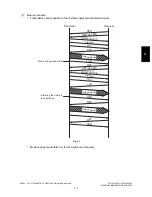
Page 47: ... and reception in the Toshiba original procedure G3 modes Fig 3 1 Mode change is possible only for the original set manually Transmtter Receiver Mode change possible Image signal Image signal Image signal Informing that there is the next page CED CFR MCF MCF MCF NSF CSI DIS NSS TSI DCS NSF CSI DIS NSS TSI DCS TCF EOM Training CFR TCF MPS DCN Training ...

Page 48: ...eived image data the receiving station informs the sending station of the occurrence of the error and the sending station sends the image data again Fig 3 2 Transmtter Receiver Image signal Image signal Image signal retransmitted Image signal 256 frames received Error occurred Only error frame retransmitted Page 1 completed Page 2 completed CED NSF CSI DIS NSS TSI DCS Training TCF CFR MCF MCF MCF ...

Page 49: ... of the presence absence of the next page or mode changes by pressing the STOP button If the STOP button is pressed anytime except during the transmission of the image data DCN is forcibly sent to terminate the communication Press the JOB STATUS button and select the transmission job to cancel then press the CANCEL button on the LCD display to cancel the memory transmission or polling transmis sio...

Page 50: ...ling etc DCS Digital Command Signal Commands to transmit using the standard facility which is selected corresponding to DIS or DTC SUB Sub address Indicates that the FIF information is a sub address in the domain on the call in side SEP Select Polling Indicates that the FIF information is a sub address for the polling mode PWD Password Indicates that the FIF information is a password for the polli...

Page 51: ... ECM mode RNR Receive Not Ready Informs that the FAX is not in the receivable state ECM mode PPR Partial Page Request Informs that a part of page ECM block has not been received correctly The number of the frame needs to be corrected is informed by the FIF EC mode PPS Partial Page Signal Informs that a part of page ECM block or one page has been transmitted EC mode CTC Continue to Correct Replies ...

Page 52: ...f a frame Also establishes the frame synchronization A Address field Informs the address C Control field Informs if this frame is the last one in this procedure FCF FAX control field Informs the type of the binary signal FIF FAX information field Informs FAX information such as the functions FCS Frame check sequence Checks if there was any error in the transmission from A to FIF Format of F A and ...

Page 53: ... DIS 0 0 0 0 0 0 0 1 DTC 1 0 0 0 0 0 0 1 DCS x 1 0 0 0 0 0 1 SUB x 1 0 0 0 0 1 1 SEP 1 0 0 0 0 1 0 1 PWD Rx 1 0 0 0 0 0 1 1 PWD Tx x 1 0 0 0 1 0 1 CFR x 0 1 0 0 0 0 1 FTT x 0 1 0 0 0 1 0 EOM x 1 1 1 0 0 0 1 MPS x 1 1 1 0 0 1 0 EOP x 1 1 1 0 1 0 0 MCF x 0 1 1 0 0 0 1 RTN x 0 1 1 0 0 1 0 PIP x 0 1 1 0 1 0 1 PIN x 0 1 1 0 1 0 0 PRI EOM x 1 1 1 1 0 0 1 PRI MPS x 1 1 1 1 0 1 0 PRI EOP x 1 1 1 1 1 0 0 D...

Page 54: ...ta communication to follow When the receiving side detects an error in the TCF signal it transmits an FTT signal to the transmitting side to request the retraining When there is no error the receiving side transmits a CFR signal The TCF signal transmits all zeros for 1 5 seconds at the same modem speed as that for the training signal Alternation of ABAB Scrambled binary data 1 Segment 1 Segment 2 ...

Page 55: ...ps 12 0 kbps 9 6 kbps 7 2 kbps 4 8 kbps 2 4 kbps The modulating speed baud rate 4 can be selected from 2 400 3 000 3 200 symbol sec man datory or 2 743 2 800 3 429 symbol sec option The data rate can be set more accurately than the conventional modem Notes 1 ECM is used in the V 34 procedure If the setting for the ECM transmission reception of the user data is set to Not performed the V 8 procedur...

Page 56: ... After the information about the modem capa bility is exchanged the receiver determines the modulation speed based on the result of reception of the probing signal which was sent by the transmitter To determine the image transmission speed the transmitter sends a training signal The optimum image transmission speed is determined according to the training signal received The pre FAX transmission wh...

Page 57: ...sender is a FAX machine in the auto matic calling mode Call Menu signal CM Mainly indicates an available modulation method such as V 21 V 27ter V 29 V 17 V 34 etc Modulated by V 21 L 1 Transmission rate 300 bps CM terminator CJ Indicates the detection of the JM signal or the termination of CM signal Modulated by V 21 L 1 Transmission rate 300 bps Call Indicator signal CI Indicates the general comm...

Page 58: ...by 1200 Hz tone sig nal is a signal that shifts the phase B 180 Tone Line probing signal L1 L1 Tone signal to analyze the line characteristics by probing Probing is to examine the line characteristics Tone signal between 150 Hz and 3 750 Hz in units of 150 Hz Line probing signal L2 L2 Signal name Abbreviation Function Remarks INFO sequence INFO0a Informs the modem capability such as the modulating...

Page 59: ...re made in this phase Transmitter receiver Signal name Abbreviation Function Remarks S signal S Short training is a signal made as the result of phase transition of S signal PP signal PP Used by the modem of the receiver to train the equalizer TRN signal TRN Used by the receiver to deter mine the transmission rate Signal name Abbreviation Function Remarks PPh signal PPh Used by the modem of the ot...

Page 60: ...er It selects the available mode from the received NSF and specifies the mode for the reception Transmitting Subscriber ID TSI Informs the telephone number of the transmitter Digital Command Signal DCS Specifies the mode that can be used for the communica tion 1 Declares to switch to the high speed procedure 1 is sent continuously Signal name Abbreviation Function Remarks Non Standard Facilities N...

Page 61: ...ter Image data Image data are sent Transmitter Signal name Abbreviation Function Remarks S signal S Short training is a signal that makes a transition from phase S signal PP signal PP Used by the modem of the receiver to train the equalizer B1 sequence B1 Scrambled data frame to be sent when the startup process is completed Signal name Abbreviation Function Remarks Image data Image data Encoded im...

Page 62: ...raining signal ALT signal ALT E sequence E End of procedure signal PPS EOP The transmission of one page is completed Flag flags Maintains the synchroniza tion 7E H Disconnection signal DCN Informs to disconnect the line Signal name Abbreviation Function Remarks Sh signal Sh Short training signal ALT signal ALT E sequence E Flag flags Maintains the synchroniza tion 7E H Message confirmation MCF Ind...

Page 63: ... important signals in the procedure Late start The receiver cannot detect CM signal while it is sending the ANSam signal Therefore it sends a DIS signal to inform the availability of V 8 support The transmitter sends a CI signal that causes the receiver to send another ANSam signal which makes the receiver move to the V 8 procedure Fig 3 8 Transmitter Receiver Line closed DIS cannot be recognized ...

Page 64: ...reserved DIALING COMMUNICATION CONTROL 3 22 Multi page sequence In the same manner as the T 30 procedure the transmitter sends a PPS MPS signal after send ing the image data The receiver sends an MCF signal and moves to the next page transmission Fig 3 9 Transmitter Receiver ...

Page 65: ...0 1160 1260 DIALING COMMUNICATION CONTROL 3 23 3 Mode change The transmitter and receiver send a PPS EOM signal and an MCF signal respectively Then the receiver and transmitter send a DIS signal and a DCS signal respectively to change the mode Fig 3 10 Transmitter Receiver ...

Page 66: ...UNICATION CONTROL 3 24 Change of the image transmission speed by the receiver The receiver sends a PPh signal responding to an Sh signal sent from the transmitter Then the image transmission speed is determined according to the MPh sequence sent from the both modems Fig 3 11 Transmitter Receiver ...

Page 67: ... CONTROL 3 25 3 Change of the image transmission speed by the transmitter The transmitter sends a PPh signal after sending the image data The receiver returns a PPh sig nal Then the image transmission speed is determined according to the MPh sequence sent from the both modems Fig 3 12 Transmitter Receiver ...

Page 68: ...When the operator has learned that the caller is sending a FAX he has to per form the manual reception operation 3 3 3 FAX mode This mode is selected when the telephone circuit is used only for FAX communication When the FAX mode is selected and a calling signal comes from the exchange the FAX reception operation starts automatically without ringing the telephone ringer In the FAX mode a calling n...

Page 69: ...TRICAL CIRCUITS 4 1 Configuration e STUDIO2500c 3500c 3510c Fig 4 1 SYS FAX I F harness GD 1210 Speaker MDM board FAX board GD 1160 NCU 1 FAX PWR board NCU 2 FAX ASIC TENNESEE V 34 modem FM336PLUS V 34 modem FM336PLUS CPU 95C265 CODEC MN86064 CODEC MN86064 Flash ROM 4Mbit x 1 Memory 1Mbit x 6 Memory 1Mbit x 4 08 04 ...

Page 70: ...520C 6520C 6530C e STUDIO5540C 6540C 6550C e STUDIO205L 255 305 355 455 e STUDIO555 655 755 855 e STUDIO206L 256 306 356 456 e STUDIO556 656 756 856 Fig 4 2 FAX ASIC TENNESEE V 34 modem FM336PLUS V 34 modem FM336PLUS NCU 1 NCU 2 SYS FAX I F harness GD 1250 GD 1270 Speaker CPU 95C265 CODEC MN86064 CODEC MN86064 Flash ROM 4Mbit x 1 Memory 4Mbit x 2 Memory 4Mbit x 1 GD 1260 MDM board FAX board 11 12 ...

Page 71: ...s the line current and ring signal and monitors the line The NCU board is connected to CN501 on the FAX board It can be also connected optionally to CN502 The description in this section is based on the NCU board for Line 1 NA TW models Fig 4 3 0 1 0 1 IC53 IC52 T1 RLY2 CML relay CNG signal detection circuit Line External telephone CN10 CN11 CN9 CML ANSDET TXOUT RXIN REVB REVA CI LD a2 b2 Lb La NC...

Page 72: ... RLY4 Relay DB1 NCU board Lb La a2 b2 CN3 Line External telephone Line current detection circuit IC5 Analog switch IC3 Analog switch Ring signal detection circuit CNG signal detection circuit Dial pulse generation circuit DC consumption circuit AG IC6 IC6 IC4 T1 IC4 0 1 0 1 CN4 FAX board CI ANSDET RLADJ1 RLADJ2 TXOUT LD ATT3DB CML REVB REVA RXIN ...

Page 73: ...l When the CML1 sig nal or ATT3DB1 signal goes HIGH the analog switch is turned ON Turning ON the CML relay and analog switch allow the MODEM to be connected to the line Values in are for GD 1250 1270 in case that the descriptions vary between GD 1210 and GD 1250 1270 Signal Name Type Active Description Destination CML1 O H Line 1 CML Relay Control Signal RLY2 IC51 ATT3DB1 O H Line 1 Attenuator Co...

Page 74: ...gnals The analog switch is switched according to the states of the RLADJ11 and RLADJ21 signals Turning ON the CML relay and analog switch allow the MODEM to be connected to the line Values in are for GD 1250 1270 in case that the descriptions vary between GD 1210 and GD 1250 1270 Signal Name Type Active Description Destination CML1 O H Line 1 CML Relay Control Signal RLY3 IC3 ATT3DB1 O H Line 1 At...

Page 75: ... line to the MODEM side To generate the dial pulse the ASIC makes the LD1 signal become HIGH to turn ON Q53 This allows the photo coupler to come on and the current flows through the DB1 to send the dial pulses to the line Values in are for GD 1250 1270 in case that the descriptions vary between GD 1210 and GD 1250 1270 Signal Name Type Active Description Destination LD1 O H Line 1 Dial Pulse Gene...

Page 76: ...erate the dial pulses the ASIC makes the LD1 signal become HIGH to turn ON Q6 This allows the photocou pler to come on and the current flows through the line for sending a dial attempt Values in are for GD 1250 1270 in case that the descriptions vary between GD 1210 and GD 1250 1270 Signal Name Type Active Description Destination LD1 O H Line 1 Dial Pulse Generation Signal Q6 T1 AG CML1 LD1 3 4 AG...

Page 77: ...photocoupler is repeatedly turned ON OFF This allows the REVA1 and REVB1 to be the pulse signals and input to the ASIC then the dial tone is detected When the handset is lifted from the external telephone current also flows through the line and the pho tocoupler is turned ON OFF then the off hook state is detected Values in are for GD 1250 1270 in case that the descriptions vary between GD 1210 an...

Page 78: ...n a dial tone is input from the telephone line current flows through the line The line current detec tion IC sends REVA1 and REVB1 to the ASIC as pulse signals This allows a dial tone to be detected Values in are for GD 1250 1270 in case that the descriptions vary between GD 1210 and GD 1250 1270 Signal Name Type Active Description Destination REVA1 I Line 1 Current Detection Signal IC29 IC26 REVB...

Page 79: ...to the telephone line When a ring signal is input from the telephone line the photocoupler is repeatedly turned ON OFF This allows the CI1 signal to become a pulse signal and input to the ASIC on the FAX board thereby detect ing the ring signal Values in are for GD 1250 1270 in case that the descriptions vary between GD 1210 and GD 1250 1270 Signal Name Type Active Description Destination CI1 I Li...

Page 80: ...gnal is input from the telephone line the photocoupler is repeatedly turned ON OFF This allows Q5 to be turned ON OFF and the CI1 signal to become a pulse signal and input to the ASIC on the FAX board thereby detecting the ring signal Values in are for GD 1250 1270 in case that the descriptions vary between GD 1210 and GD 1250 1270 Signal Name Type Active Description Destination CI1 I Line 1 CI De...

Page 81: ...6 1 1 2 3 6 1 1 2 2 6 7 3 1 13 7 5 6 2 4 15 14 9 11 10 3 6 2 IC29 IC26 ASIC IC45 IC12 CPU 13 14 15 12 1 5 2 4 11 10 9 RING TXOUT1 RXIN1 1 43 12 9 10 MON 26 11 CML1 21 ATT3DB1 22 SP SP Speaker IC9 IC2 Analog switch IC10 IC1 IC3 Analog switch AG SG T1 IC53 IC52 AG CN9 CN501 0 1 0 8 12 1 4 9 0 1 0 1 0 1 IC51 Analog switch RLY2 CML relay FAX board AG Q51 12V R273 R272 R59 R71 R67 R271 R270 R268 R267 R...

Page 82: ...line to the MODEM side For the line path switching control refer to P 4 5 4 2 2 Line path switching control circuit The relation between the signal levels and monitoring signals is as follows The monitoring signal selected by IC3 is input to the analog switch IC9 IC2 to select the output sound volume The sound volume is selected by switching IC8 according to the VOLSEL0 2 signals output from the A...

Page 83: ...put to the speaker Values in are for GD 1250 1270 in case that the descriptions vary between GD 1210 and GD 1250 1270 Sound volume VOLSEL2 VOLSEL1 VOLSEL0 Max 7 LOW LOW LOW 6 LOW LOW HIGH 5 LOW HIGH LOW 4 LOW HIGH HIGH 3 HIGH LOW LOW 2 HIGH LOW HIGH Min 1 HIGH HIGH LOW Silent 0 HIGH HIGH HIGH Signal Name Type Active Description Destination SP SEL O H Line Tone Selection Signal IC3 MON O H Ring Ton...

Page 84: ...GD 1210 1250 1270 1160 1260 2006 2011 TOSHIBA TEC CORPORATION All rights reserved ELECTRICAL CIRCUITS 4 16 4 3 PC Boards 1 PWA F FAX 631 GD 1210 Fig 4 15 08 04 ...

Page 85: ... 2006 2011 TOSHIBA TEC CORPORATION All rights reserved GD 1210 1250 1270 1160 1260 ELECTRICAL CIRCUITS 4 17 4 2 PWA F FAX 670 GD 1250 1270 Fig 4 16 08 04 ...

Page 86: ...60 1260 2006 2011 TOSHIBA TEC CORPORATION All rights reserved ELECTRICAL CIRCUITS 4 18 3 PWA F NCU 631 NAD TWD SAD GD 1210 GD 1250 GD 1270 Fig 4 17 4 PWA F NCU 631 MJD AUD ASD CND KRD GD 1210 GD 1250 GD 1270 Fig 4 18 08 04 ...

Page 87: ...s reserved GD 1210 1250 1270 1160 1260 ELECTRICAL CIRCUITS 4 19 4 5 PWA F NCU 562 NAD TWD SAD GD 1160 PWA F NCU 631 NAD TWD SAD GD 1260 Fig 4 19 6 PWA F NCU 562 MJD AUD ASD CND KRD GD 1160 PWA F NCU 631 MJD AUD ASD CND KRD GD 1260 Fig 4 20 08 04 ...

Page 88: ...GD 1210 1250 1270 1160 1260 2006 2011 TOSHIBA TEC CORPORATION All rights reserved ELECTRICAL CIRCUITS 4 20 7 PWA F MDM 563 GD 1160 Fig 4 21 8 PWA F MDM 671 GD 1260 Fig 4 22 08 04 ...

Page 89: ... 2006 2011 TOSHIBA TEC CORPORATION All rights reserved GD 1210 1250 1270 1160 1260 ELECTRICAL CIRCUITS 4 21 4 9 PWA F FAX POWER 631 GD 1210 Fig 4 23 08 04 ...

Page 90: ...GD 1210 1250 1270 1160 1260 2006 2011 TOSHIBA TEC CORPORATION All rights reserved ELECTRICAL CIRCUITS 4 22 ...

Page 91: ...hod Manual transmission Monitor dialing Direct dialing with the digital keys Phone book dialing Delayed transmission Multi transmission Redialing Recording paper size Recording paper size How to change the recording paper size Automatic manual reception How to switch the automatic and manual reception How the machine works and how to operate it when a FAX is received in these modes Other functions...

Page 92: ...GD 1210 1250 1270 1160 1260 2006 2011 TOSHIBA TEC CORPORATION All rights reserved INSTALLATION 5 2 ...

Page 93: ......

Page 94: ......

Reviews: