background image

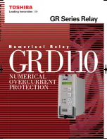
GRD110


4

PROTECTION FUNCTIONS 

Phase Fault Overcurrent Protection 

Models GRD110-400, 420, 500 and -520 can provide 

two or three phase overcurrent protection. Each provides 

four  independent  overcurrent  thresholds.  The  first 

and second thresholds may be set for inverse time or 

definite  time  operation.  If  inverse  time  is  selected, 

then  any  one  of  nine  curves  may  be  chosen, 

including  IEC  and  IEEE/  ANSI  standard 

characteristics.  Further,  user  configurable  curve  is 

available, if required. See Figure 1. 
The  first  and  second  thresholds  have  a 

programmable  reset  feature,  selectable  for 

instantaneous, definite time or dependent time reset. 

This feature can be used to protect against flashing 

fault  conditions,  or  to  grade  correctly  with 

electromechanical overcurrent relays. 
The  other  overcurrent  thresholds  may  be  set  for 

definite  time,  or  instantaneous  operation.  These 

elements  are  immune  to  the  effects  of  transformer 

magnetising inrush and dc offset transient over-reach. 
All  elements  can  be  inhibited  by  binary  input  signals 

for  operation  in  blocked  overcurrent  schemes  and 

busbar zone blocking protection. 

Earth Fault Protection 

The standard earth fault protection is available in all 

models,  and  provides  four  independent  overcurrent 

thresholds. Protection functionality is the same as for 

the  phase  fault  elements,  only  with  more  sensitive 

current thresholds. 
For  models  GRD110-110,  400  and  -500  the  earth 

fault  quantity  is  measured  directly,  either  by 

connecting the input in the residual circuit of the

phase 

CTs,  or,  as  is  recommended  for  more  sensitive 

settings,  using  a  dedicated  core  balance  earth  fault 

CT. For model GRD110-420 and -520, the standard 

earth  fault  quantity  is  derived  internally  from  the 

residual sum of the three phases. 

Sensitive Earth Fault Protection (SEF) 

GRD110-110,  420  and  -520  provide  earth  fault 

protection  with  more  sensitive  settings  for  use  in 

applications  where  the  fault  current  magnitude  may 

be  very  low.  A  2-stage  overcurrent  function  is 

provided,  with  the  first  stage  programmable  for 

inverse  time  or  definite  time  operation.  The  second 

stage provides definite time operation and runs after 

operation  of  the  first  stage.  Three  additional 

overcurrent  thresholds  are  provided,  each  with  a 

definite time delay. 
The  sensitive  earth  fault  element  includes  a  digital 

filter  which  rejects  all  harmonics  other  than  the 

fundamental power system frequency. 
The sensitive earth fault quantity is measured directly, 

using a dedicated core balance earth fault CT. 
This input can also be used in transformer restricted 

earth fault applications, by the use of external metrosils 

and setting resistors. 

Phase Undercurrent Protection 

Protection against loss of load is provided by the phase 

undercurrent protection. Two independent thresholds 

are provided, each with a programmable definite time 

delay. 

Thermal Overload Protection 

The thermal overload feature provides protection for 

cables and other plant against the effects of prolonged 

operation under excess load conditions. A thermal replica 

algorithm is applied to create a model for the thermal 

characteristics  of  the  protected  plant.  Tripping  times 

depend not only on the level of overload current, but 

also  on  the  level  of  prior  load  current,  the  thermal 

replica providing ‘memory’ of previous conditions. 
The thermal characteristics of the system are defined 

by entering settings for full load current and thermal 

time constant. The GRD110 issues a trip according to 

the  ‘cold’  and  ‘hot’  curves  specified  in  IEC60255-8 

(see Figure 2), to prevent the protected system from 

exceeding its thermal capacity. The cold curve tripping 

times are applicable when the system is first energised, 

while  the  hot  curves  are  relevant  when  the  system 

has  already  been  carrying  some  prior  load  for  a 

period of time. An alarm output is also available to 

give  early  warning  of  high  load  current,  set  as  a 

percentage of thermal capacity. 

Negative Phase Sequence Overcurrent 

Protection (NPS) 

NPS  protection  can  be  used  in  applications  where 

certain  fault  conditions  may  not  be  detected  by  the 

normal  phase  and  earth  overcurrent  protections,  for 

example, in the case of a relay applied on the delta 

side  of  a  delta-star  transformer,  to  detect  an  earth 

fault on the star side. Alternatively, NPS can be used 

to  protect  a  three  phase  motor  against  the  severe 

overheating  which  results  from  operating  with  an 

unbalanced supply. 
Two independent thresholds are provided, each with 

a programmable definite time delay. 

Broken Conductor Protection 

The unbalance condition caused by an open circuited 

conductor is detected by the broken conductor protection. 

An  unbalance  threshold  with  programmable  definite 

time delay is provided. 

Circuit Breaker Fail Protection (CBF) 

Two  stage  CBF  protection  provides  outputs  for  re-

tripping  of  the  local  circuit  breaker  and/or  back-

tripping  to  upstream  circuit  breakers.  The  CBF 

08.02.18 GRD110_CS3.indd

Summary of Contents for GRD110

Page 1: ......

Page 2: ...t inputs fitted see Table 1 Table 1 GRD110 Models Model Configuration GRD110 110 Earth Fault and Sensitive Earth Fault GRD110 400 Three Phase Fault and Earth Fault GRD110 420 Three Phase Fault Earth Fault and Sensitive Earth Fault GRD110 500 Three Phase Fault and Earth Fault and Auto reclose GRD110 520 Three Phase Fault Earth Fault Sensitive Earth Fault and Auto reclose All models include multiple...

Page 3: ...r 9 9 9 9 Circuit Breaker Fail 50BF 9 9 9 9 Inrush current detector 9 9 Cold Load Protection 9 9 9 9 Auto reclose 79 9 9 Trip circuit supervision 9 9 9 9 9 Self supervision 9 9 9 9 9 CB State Monitoring 9 9 9 9 9 Trip Counter Alarm 9 9 9 9 9 Iy Alarm 9 9 9 9 CB Operate Time Alarm 9 9 9 9 9 Four settings groups 9 9 9 9 9 Metering 9 9 9 9 9 Fault records 9 9 9 9 9 Event records 9 9 9 9 9 Disturbance...

Page 4: ...ics other than the fundamental power system frequency The sensitive earth fault quantity is measured directly using a dedicated core balance earth fault CT This input can also be used in transformer restricted earth fault applications by the use of external metrosils and setting resistors Phase Undercurrent Protection Protection against loss of load is provided by the phase undercurrent protection...

Page 5: ...gisation This is achieved by a Cold Load Settings Group in which the user can programme alternative settings Normally the user will choose higher current settings and or longer time delays and or disable elements altogether within this group Auto Reclose GRD110 500 and 520 provides an auto reclose function Four independent sequences are provided one for each of the following Phase fault Earth faul...

Page 6: ...g Time s MI VI EI STI I º ª u c Is I k TMS t 1 D RTMS Is I kr tdo u º ª E 1 Inverse time operate function Dependent time reset function Constants for dependent time curves Curve Description k D C kr E IEC Normal Inverse NI 0 14 0 02 0 IEC Very Inverse VI 13 5 1 0 IEC Extremely Inverse EI 80 2 0 UK Long Time Inverse LTI 120 1 0 IEEE Moderately Inverse MI 0 0515 0 02 0 114 4 85 2 IEEE Very Inverse V...

Page 7: ...90 prior load 0 001 0 01 0 1 1 10 100 1000 1 10 Overload Current Multiple of k IFLC Operate Time minutes W 100 W 50 W 20 W 10 W 5 W 2 W 1 º ª 2 2 2 FLC I k I I Ln t W º ª 2 2 2 2 FLC P I k I I I Ln t W IEC60255 8 Cold Curve IEC60255 8 Hot Curve t time to trip for constant overload current I seconds I overload current largest phase current pu IP previous load current pu k IFLC or IT thermal overloa...

Page 8: ...GRD110 110 The operating time monitor records the time between issuing the tripping signal and the phase currents falling to zero An alarm is issued when the operate time for any phase exceeds a user defined setting The CB condition monitoring functions are triggered each time a trip is issued and they can also be triggered by an external device via a binary input METERING AND RECORDING Metering T...

Page 9: ...ion with a substation control and monitoring system and is used to transfer measurand data status data and general commands between the relay and the control system Relay Setting The user can modify relay settings either using the front panel keypad or using the RSM100 software from a local or remote PC Password protection is available for added security Four settings groups are provided allowing ...

Page 10: ...GRD110 10 Figure 5 Relay Setting and Monitoring System PC Displays PC DISPLAY Setting Event record Metering Data analysis Fault record ...

Page 11: ... d 0 5W per input at 110Vdc Current Transformer Requirements Phase Inputs Typically 5P20 with rated burden according to load refer to manual for detailed instructions Standard Earth Inputs Core balance CT or residual connection of phase CTs Sensitive Earth Inputs Core balance CT Phase Overcurrent Protection P F 1 st 2 nd Overcurrent threshold OFF 0 04 5 00A in 0 01A steps 1A rating OFF 0 2 25 0A i...

Page 12: ... 1 RTMS 0 010 1 500 in 0 001 steps Stage 2 DTL delay for SEF 1 st 0 00 300 00s in 0 01s steps SEF 3rd 4th thresholds OFF 0 004 1 000A in 0 001A steps 1A rating OFF 0 02 5 00A in 0 01A steps 5A rating DTL delay 0 00 300 00s in 0 01s steps Phase Undercurrent Protection Undercurrent 1 st 2 nd threshold OFF 0 10 2 00A in 0 01A steps 1A rating OFF 0 5 10 0A in 0 1A steps 5A rating DTL Delay 0 00 300 00...

Page 13: ...ure connector female Rear Communication port remote PC RS485 Connection Multidrop max 32 relays Cable type Twisted pair cable with shield Cable length 1200m max Connector Screw terminals Isolation 2kVac for 1 min Transmission rate 64kpbs for RSM system 9 6 19 2kbps for IEC60870 5 103 Rear Communication port remote PC Fibre Optic for IEC60870 5 103 option Cable type Graded index multi mode 62 5 125...

Page 14: ... Disturbance IEC60255 22 3 Class 3 IEC61000 4 3 EN61000 4 3 Field strength 10V m for frequency sweeps of 80MHz to 1GHz and 1 4GHz to 2 7GHz Additional spot tests at 80 160 450 900 1850 and 2150MHz Fast Transient Disturbance IEC60255 22 4 IEC61000 4 4 EN61000 4 4 4kV 2 5kHz 5 50ns applied to all inputs Surge Immunity IEC60255 22 5 IEC61000 4 5 EN61000 4 5 1 2 50Ps surge in common differential modes...

Page 15: ...odel 420 Three phase earth and sensitive earth fault 420 Model 500 Three phase and earth fault with auto reclose 500 Model 520 Three phase earth and sensitive earth fault with auto reclose 520 CT Rating 1A 1 5A 2 Frequency 50Hz 1 60Hz 2 DC auxiliary supply rating 110V 125V 1 220V 250V 2 48V 54V 60V 3 Rear communication port RS485 1 Fibre optic 2 Dual RS485 3 GRD110 A ...

Page 16: ...B7 㪙㪦㪉 A6 B6 B8 A8 㪙㪦㪊 A9 B9 A10 B10 㪙㪦㪋 A11 B11 A13 B13 㪙㪦㪌 A12 B12 A14 B14 㪙㪦㪍 A15 B15 A16 B16 㪙㪦㪎 B17 A17 FAIL A18 B18 TB3 B4 8 7 BUSBAR 6 CB FRAME EARTH IE ISE TB1 5 CT Core balance CT P B1 BI1 B2 BI2 B3 BI3 A2 A3 B4 BI4 A4 B5 BI5 A5 B6 BI6 A6 B7 BI7 A7 B8 BI8 A8 TB2 A1 N BI1 COMMAND BI2 COMMAND BI3 COMMAND BI4 COMMAND BI5 COMMAND BI6 COMMAND BI7 COMMAND BI8 COMMAND TB4 A2 COM2 B COM2 A RS485 ...

Page 17: ... A8 㪙㪦㪊 A9 B9 A10 B10 㪙㪦㪋 A11 B11 A13 B13 㪙㪦㪌 A12 B12 A14 B14 㪙㪦㪍 A15 B15 A16 B16 㪙㪦㪎 B17 A17 FAIL A18 B18 BUSBAR 4 3 2 6 5 CT CB FRAME EARTH 8 7 IA IB IC IN TB1 1 TB3 B4 P B1 BI1 B2 BI2 B3 BI3 A2 A3 B4 BI4 A4 B5 BI5 A5 B6 BI6 A6 B7 BI7 A7 B8 BI8 A8 TB2 A1 N BI1 COMMAND BI2 COMMAND BI3 COMMAND BI4 COMMAND BI5 COMMAND BI6 COMMAND BI7 COMMAND BI8 COMMAND TB4 A2 COM2 B COM2 A RS485 I F for IEC60870 5...

Page 18: ... A9 B9 A10 B10 㪙㪦㪋 A11 B11 A13 B13 㪙㪦㪌 A12 B12 A14 B14 㪙㪦㪍 A15 B15 A16 B16 㪙㪦㪎 B17 A17 FAIL A18 B18 TB3 B4 4 3 2 6 5 FRAME EARTH 8 7 IA IB IC ISE TB1 1 BUSBAR CB CT Core balance CT P B1 BI1 B2 BI2 B3 BI3 A2 A3 B4 BI4 A4 B5 BI5 A5 B6 BI6 A6 B7 BI7 A7 B8 BI8 A8 TB2 A1 N BI1 COMMAND BI2 COMMAND BI3 COMMAND BI4 COMMAND BI5 COMMAND BI6 COMMAND BI7 COMMAND BI8 COMMAND TB4 A2 COM2 B COM2 A RS485 I F for ...

Page 19: ...4 5 TB3 Rear view E TB1 TB2 TB4 TB1 TB2 TB3 Screw terminal M3 5 Ring TB4 Screw terminal TB4 is provided only for dual RS485 model Terminal block TB3 A1 B1 A18 B18 1 2 3 4 5 6 TB1 TB2 A1 B1 A10 B10 7 8 A1 A3 TB4 B1 B3 104 2 5 8 IN SERVICE TRIP ALARM VIEW RESET Front view END CEL CAN ENTER 185 2 32 15 6 Side view ...

Page 20: ...T1 The data given in this catalog are subject to change without notice Power Systems Company 1 1 SHIBAURA 1 CHOME MINATO KU TOKYO 105 8001 JAPAN PHONE 81 3 3457 3644 FAX 81 3 5444 9168 http www toshiba relays com ...

Reviews: