GRD130
5
USER INTERFACE
Relay Front Panel
A user friendly interface is provided on the relay front
panel. A menu-based system provides for easy
programming of relay functions and access to real-
time and stored data. The front panel includes the
following features.
16 character, 2-line LCD with backlight.
6 LEDs.
Keypad.
RS232C serial port for connection of local PC.
Local PC Connection
The user can communicate with the GRD130 from a
local PC via the RS232C port on the front panel. Using
RSM100 software, the user can view and modify
settings, monitor real-time metering and analyse
recorded data.
Relay Setting and Monitoring (RSM)
GRD130 can be connected to the RSM system via the
rear mounted serial communications port, using either
RS485 or fibre optic connections (specified at time of
order). Using RSM100 software, the user can view and
modify settings, monitor real-time metering and analyse
recorded data.
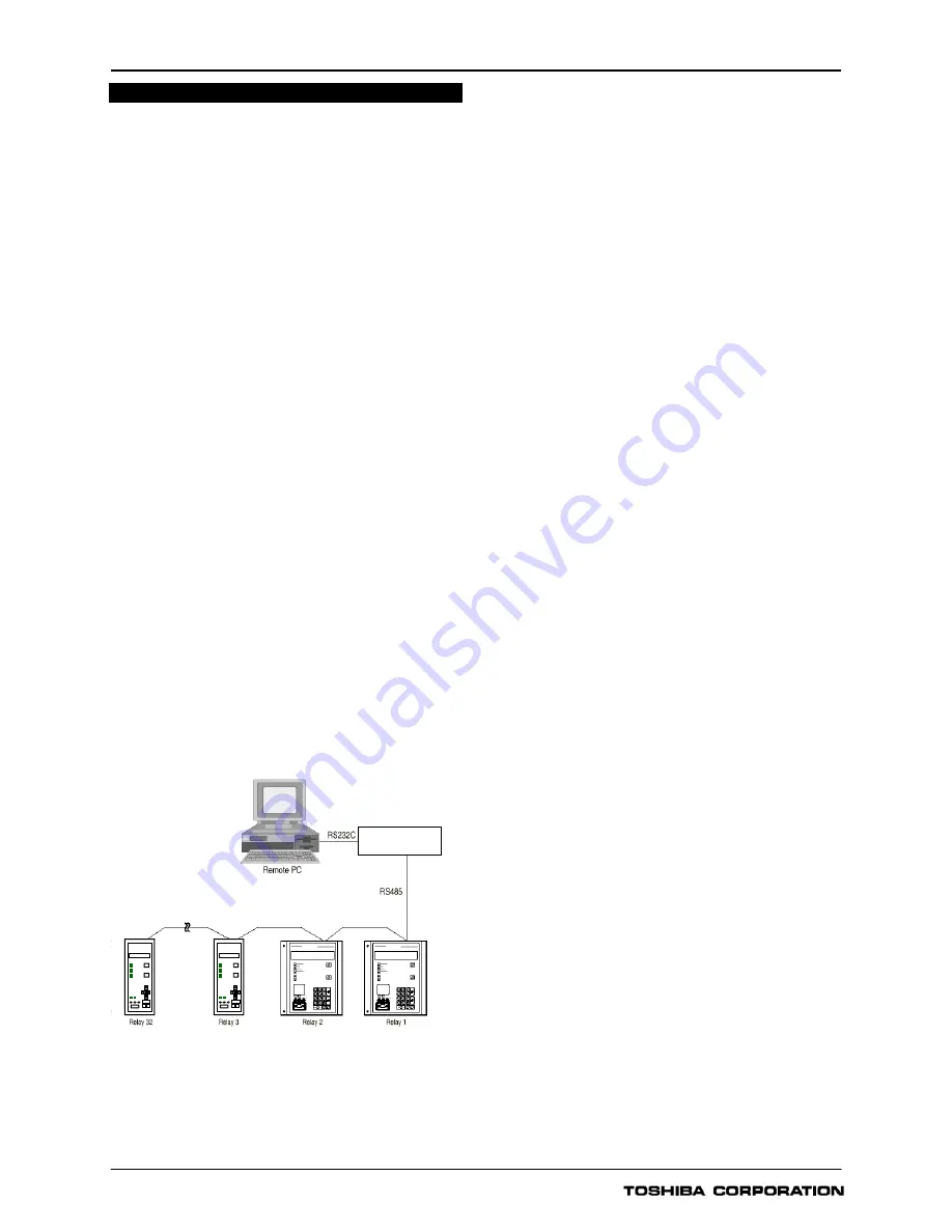
A maximum of 32 x 8 relays can be connected to the
remote PC in multi-drop mode, by connection via a
protocol converter G1PR2, with a maximum data
transmission rate of 64kbps. The G1PR2 can be
provided with maximum 8 ports and each port
supports maximum 32 relays addressing.
Figure 3 - Relay Setting and Monitoring System
Figure 3 and 4 show the configuration of the RSM
system and typical displays from the RSM100 software.
IEC60870-5-103 Communications
GRD130 supports the IEC60870-5-103
communication protocol. This protocol is used for
communication with a substation control and
monitoring system and is used to transfer measurand
data, status data and general commands between the
relay and the control system.
Relay Setting
The user can modify relay settings either using the
front panel keypad or using the RSM100 software from
a local or remote PC. Password protection is available
for added security.
Four settings groups are provided, allowing the user to
set one group for normal conditions, while the other
groups may be set to cover alternative operating
conditions.
Using the RSM software, the user can create a settings
file on a PC (without being connected to a relay), and
store the file ready for download to a relay at a later
date.
Binary Outputs
GRD130 provides eight binary output contacts for
tripping and alarm, of which seven are user
programmable. Each of the programmable binary
outputs is driven via a logic gate which can be
programmed for OR gate or AND gate operation.
Further, each output has a programmable reset
characteristic, settable for instantaneous drop-off,
delayed drop-off, or for latching operation. If latching
operation is selected then an operated relay must be
reset by the user, either by pressing the RESET
button, by energising a binary input which has been
programmed for ‘Remote Reset’ operation, or by a
communications command.
Binary Inputs
GRD130 provides eight programmable binary inputs.
Each binary input is individually user-programmable
for normal or inverted operation and for delayed pick-
up and/or drop-off. Each input can also be used to
switch relay operation to a different settings group.
General purpose alarm functions are also included.
The user can define a text message for each alarm.
Then when inputs associated with that alarm are raised,
the defined text is displayed on the LCD.
G1PR2
Protocol converter
Summary of Contents for GRD130
Page 1: ......


