6 F 2 T 0 1 7 2
IDMT characteristics are not fully utilised. In this case, definite time overcurrent protection is
applied. The operating time can be constant irrespective of the magnitude of the fault current.
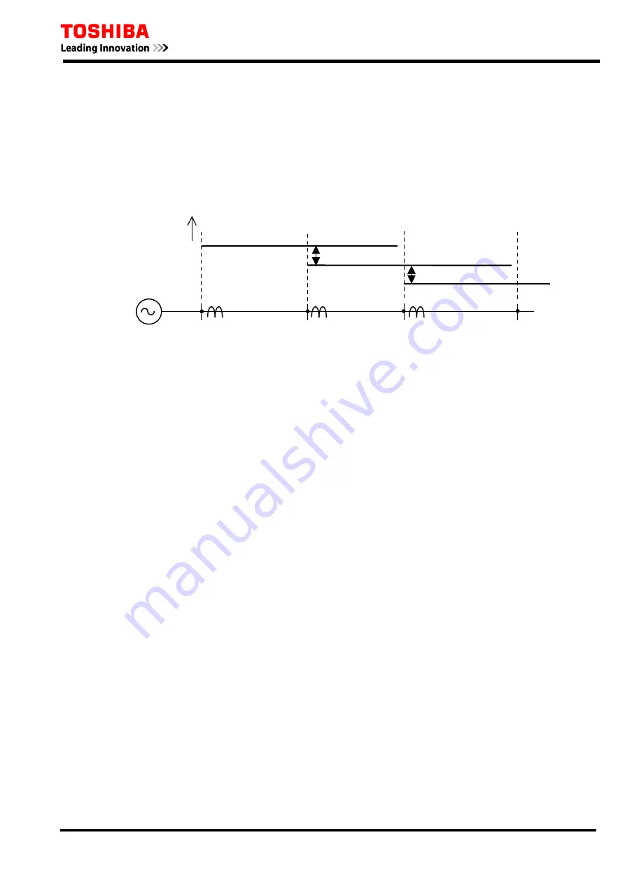
The definite time overcurrent protection consists of instantaneous overcurrent measuring elements
OC1 and EF1 and delayed pick-up timers started by the elements, and provides selective protection
with graded setting of the delayed pick-up timers. Thus, the constant time coordination with the
downstream section can be maintained as shown in Figure 2.1.4 As is clear in the figure, the nearer
to the power source a section is, the greater the delay in the tripping time of the section. This is
undesirable particularly where there are many sections in the series.
Operate time
T
C
T
C
A
B
C
Figure 2.1.4 Definite Time Overcurrent Protection
2.1.3 Scheme Logic
Figure 2.1.5 and Figure 2.1.6 show the scheme logic of the phase fault and earth fault overcurrent
protection with selective definite time or inverse time characteristic.
The definite time protection is selected by setting [MOC1] and [MEF1] to “D”. Definite time
overcurrent elements OC1-D and EF1-D are enabled for phase fault and earth fault protection
respectively, and trip signal OC1 TRIP and EF1 TRIP are given through the delayed pick-up timer
TOC1 and TEF1.
The inverse time protection is selected by setting [MOC1] and [MEF1] to either “IEC”, “IEEE” or
“US” according to the IDMT characteristic to employ. Inverse time overcurrent elements OC1-I
and EF1-I are enabled for phase fault and earth fault protection respectively, and trip signal OC1
TRIP and EF1 TRIP are given.
ICD is the inrush current detector ICD, which detects second harmonic inrush current during
transformer energisation etc. , and can block the OC1-D element by the scheme switch [OC1-2F]
respectively. See Section 2.9.
The signals OC1 HS and EF1 HS are used for blocked overcurrent protection and blocked busbar
protection (refer to Section 2.12).
These protections can be disabled by the scheme switches [OC1EN] and [EF1EN] or binary input
signals OC1 BLOCK and EF1 BLOCK.
OC2 and EF2 are provided with the same logic of OC1 and EF1.
12
Summary of Contents for GRE110
Page 183: ...6 F 2 T 0 1 7 2 Appendix B Signal List 184 ...
Page 191: ...6 F 2 T 0 1 7 2 Appendix C Event Record Items 192 ...
Page 196: ...6 F 2 T 0 1 7 2 Appendix D Binary Output Default Setting List 197 ...
Page 199: ...6 F 2 T 0 1 7 2 Appendix E Relay Menu Tree 200 ...
Page 210: ...6 F 2 T 0 1 7 2 Appendix F Case Outline 211 ...
Page 211: ...6 F 2 T 0 1 7 2 Case Outline for model 400 401 420 421 820 and 821 212 ...
Page 212: ...6 F 2 T 0 1 7 2 Case Outline for model 402 and 422 213 ...
Page 213: ...6 F 2 T 0 1 7 2 Appendix G Typical External Connection 214 ...
Page 245: ...6 F 2 T 0 1 7 2 Appendix J Return Repair Form 246 ...
Page 249: ...6 F 2 T 0 1 7 2 Customer Name Company Name Address Telephone No Facsimile No Signature 250 ...
Page 250: ...6 F 2 T 0 1 7 2 Appendix K Technical Data 251 ...
Page 256: ...6 F 2 T 0 1 7 2 Appendix L Symbols Used in Scheme Logic 257 ...
Page 259: ...6 F 2 T 0 1 7 2 Appendix M Modbus Interoperability 260 ...
Page 289: ...6 F 2 T 0 1 7 2 Appendix N IEC60870 5 103 Interoperability 290 ...
Page 296: ...6 F 2 T 0 1 7 2 Appendix O PLC Default setting 297 ...
Page 298: ...6 F 2 T 0 1 7 2 Appendix P Inverse Time Characteristics 299 ...
Page 304: ...6 F 2 T 0 1 7 2 Appendix Q IEC61850 Interoperability 305 ...


