6 F 2 T 0 1 7 2
Settings
The setting elements necessary for binary output relays and their setting ranges are as follows:
Element
Range
Step
Default
Remarks
[RESET]
Ins / Dl / Dw /Lat
See Appendix C Output relay reset time. Instantaneous,
delayed, dwell or latched.
TBO
0.00 – 10.00s
0.01s
See Appendix C
3.2.4 PLC (Programmable Logic Controller) Function
GRE110 is provided with a PLC function which enables user-configurable sequence logic based
upon binary signals. The sequence logic with timers, flip-flops, AND, OR, XOR, NOT logic, etc.
can be produced by using the PC software “PLC tool” and linked to signals corresponding to relay
elements or binary circuits.
Configurable binary inputs and the initiation of fault and disturbance records can be programmed
using the PLC function. Temporary signals are provided for complicated logic or for using a
user-configured signal in many logic sequences.
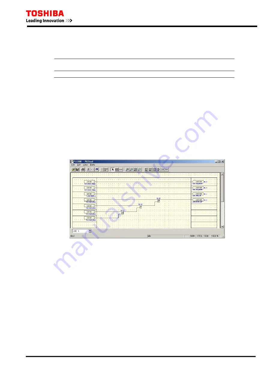
PLC logic is assigned to protection signals by using the PLC tool. For details of the PLC tool, refer
to the PLC tool instruction manual. (see 6F2S0810 Instruction manual – PLC TOOL)
Figure 3.2.4.1 Sample Screen for PLC Tool
3.3 Automatic Supervision
3.3.1 Basic Concept of Supervision
Though the protection system is in a non-operating state under normal conditions, it waits for a
power system fault to occur at any time, and must operate for the fault without fail. Therefore, the
automatic supervision function, which checks the health of the protection system during normal
operation, plays an important role. The GRE110 implements an automatic supervision function,
based on the following concepts:
•
The supervising function should not affect the protection performance.
•
Perform supervision with no omissions wherever possible.
•
When a failure occurs, the user should be able to easily identify the location of the failure.
•
Under relay failure detection , CB open control is enabled, but CB close control is disabled.
69
Summary of Contents for GRE110
Page 183: ...6 F 2 T 0 1 7 2 Appendix B Signal List 184 ...
Page 191: ...6 F 2 T 0 1 7 2 Appendix C Event Record Items 192 ...
Page 196: ...6 F 2 T 0 1 7 2 Appendix D Binary Output Default Setting List 197 ...
Page 199: ...6 F 2 T 0 1 7 2 Appendix E Relay Menu Tree 200 ...
Page 210: ...6 F 2 T 0 1 7 2 Appendix F Case Outline 211 ...
Page 211: ...6 F 2 T 0 1 7 2 Case Outline for model 400 401 420 421 820 and 821 212 ...
Page 212: ...6 F 2 T 0 1 7 2 Case Outline for model 402 and 422 213 ...
Page 213: ...6 F 2 T 0 1 7 2 Appendix G Typical External Connection 214 ...
Page 245: ...6 F 2 T 0 1 7 2 Appendix J Return Repair Form 246 ...
Page 249: ...6 F 2 T 0 1 7 2 Customer Name Company Name Address Telephone No Facsimile No Signature 250 ...
Page 250: ...6 F 2 T 0 1 7 2 Appendix K Technical Data 251 ...
Page 256: ...6 F 2 T 0 1 7 2 Appendix L Symbols Used in Scheme Logic 257 ...
Page 259: ...6 F 2 T 0 1 7 2 Appendix M Modbus Interoperability 260 ...
Page 289: ...6 F 2 T 0 1 7 2 Appendix N IEC60870 5 103 Interoperability 290 ...
Page 296: ...6 F 2 T 0 1 7 2 Appendix O PLC Default setting 297 ...
Page 298: ...6 F 2 T 0 1 7 2 Appendix P Inverse Time Characteristics 299 ...
Page 304: ...6 F 2 T 0 1 7 2 Appendix Q IEC61850 Interoperability 305 ...


