159
6
F
2
S
0
8
5
0
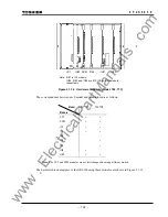
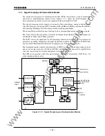
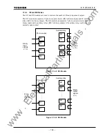
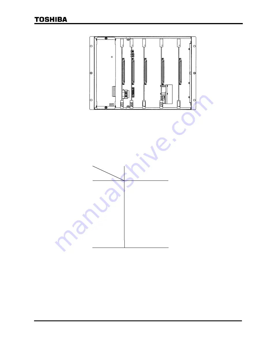
Figure 3.1.1.2 Hardware Structure (Model: 702, 712)
The correspondence between each model and module used is as follows:
Model
Module
7
01,
711
702,
712
VCT
×
×
SPM
×
×
IO1
×
×
IO2
×
×
IO3
IO4
×
IO5
×
IO6
×
HMI
×
×
Note
: The VCT and SPM modules are not interchangeable among different models.
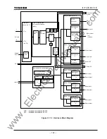
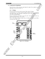
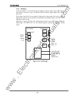
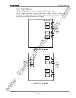
The hardware block diagrams of the GRL100 using these modules are shown in Figure 3.1.1.3.
IO
5
IO
4
IO
5
IO
4
IO#3
IO#4
SPM
IO#2
VCT
IO#1
Note: IO#1 is IO1 module.
IO#2, IO#3 and IO#4 are IO2, IO5 and IO4 module
respectively.
www
. ElectricalPartManuals
. com
Summary of Contents for GRL100-701B
Page 329: ... 328 6 F 2 S 0 8 5 0 w w w E l e c t r i c a l P a r t M a n u a l s c o m ...
Page 339: ... 338 6 F 2 S 0 8 5 0 w w w E l e c t r i c a l P a r t M a n u a l s c o m ...
Page 351: ... 350 6 F 2 S 0 8 5 0 w w w E l e c t r i c a l P a r t M a n u a l s c o m ...
Page 381: ... 380 6 F 2 S 0 8 5 0 w w w E l e c t r i c a l P a r t M a n u a l s c o m ...
Page 413: ... 412 6 F 2 S 0 8 5 0 w w w E l e c t r i c a l P a r t M a n u a l s c o m ...
Page 417: ... 416 6 F 2 S 0 8 5 0 w w w E l e c t r i c a l P a r t M a n u a l s c o m ...
Page 453: ... 452 6 F 2 S 0 8 5 0 w w w E l e c t r i c a l P a r t M a n u a l s c o m ...
Page 457: ... 456 6 F 2 S 0 8 5 0 w w w E l e c t r i c a l P a r t M a n u a l s c o m ...
Page 473: ...w w w E l e c t r i c a l P a r t M a n u a l s c o m ...


