180
6
F
2
S
0
8
5
0
(1)
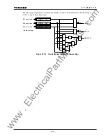
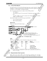
There are various messages such as "
⋅⋅⋅
err" and "
⋅⋅⋅
fail" as shown in the table in Section 6.7.2.
(2)
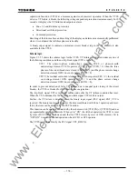
The LED is on when the scheme switch [SVCNT] is set to "ALM", and off when "ALM &
BLK" (refer to Section 3.3.11).
(3) Whether the LED is lit or not depends on the degree of voltage drop.
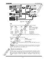
(4) The binary output relay "FAIL" will operate.
(5)
User-configurable binary output relay will operate if the supervision function and signal
applied.
(6)
The LED is on when the scheme switch [IDSV] is set to "ALM", and off when "ALM & BLK".
(7)
The LED is on when the scheme switch [CTSV] is set to "ALM", and off when "ALM & BLK".
(8)
The LED is on if the signals is assigned and the scheme switch [CTFEN] / [VTFEN] is set to
"On" or "OPT-On".
3.3.12
Trip Blocking
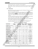
When a failure is detected by the following supervision items, the trip function is blocked as long
as the failure exists and is restored when the failure is removed:
•
A/D accuracy checking
•
Memory
monitoring
•
Watch Dog Timer
•
DC supply monitoring
•
Telecommunication channel monitoring
When a failure is detected by AC input imbalance monitoring, CT circuit current monitoring or
differential current monitoring, the scheme switch [SVCNT], [CTSV] or [IDSV] setting can be
used to determine if both tripping is blocked and an alarm is output, or, if only an alarm is output.
The CT circuit current monitoring and the differential current monitoring can be disabled by the
[CTSV] and [IDSV] respectively.
3.3.13 Setting
The setting elements necessary for the automatic supervision and their setting ranges are shown
in the table below.
Element Range
Step Default Remarks
DIFSV
0.25
−
10.00A
(0.05
−
2.00A
0.01A
0.01A
0.50A
0.10A) (
∗
)
Differential current supervision
TIDSV
0 – 60s
1s
10s
Detected time setting
RYID
0-63
0
Local relay address
RYID1
0-63
0
Remote 1 relay address
RYID2
0-63
0
Remote 2 relay address
[IDSV] OFF/ALM&BLK/ALM
OFF Differential
current
supervision
[RYIDSV]
OFF/ON
ON
Relay address supervision
[LSSV] ON/OFF
OFF
Disconnector
monitoring
[SVCNT]
ALM&BLK/ALM
ALM&BLK
Alarming and/or blocking
[CTSV]
OFF/ALM&BLK/ALM
OFF
CT circuit monitoring
(
∗
) Current values shown in parentheses are in the case of 1A rating. Other current values are in the
case of 5A rating.
For setting method, see Section 2.2.12. For the setting range of CT circuit failure detection, see
section 3.3.4.
www
. ElectricalPartManuals
. com
Summary of Contents for GRL100-701B
Page 329: ... 328 6 F 2 S 0 8 5 0 w w w E l e c t r i c a l P a r t M a n u a l s c o m ...
Page 339: ... 338 6 F 2 S 0 8 5 0 w w w E l e c t r i c a l P a r t M a n u a l s c o m ...
Page 351: ... 350 6 F 2 S 0 8 5 0 w w w E l e c t r i c a l P a r t M a n u a l s c o m ...
Page 381: ... 380 6 F 2 S 0 8 5 0 w w w E l e c t r i c a l P a r t M a n u a l s c o m ...
Page 413: ... 412 6 F 2 S 0 8 5 0 w w w E l e c t r i c a l P a r t M a n u a l s c o m ...
Page 417: ... 416 6 F 2 S 0 8 5 0 w w w E l e c t r i c a l P a r t M a n u a l s c o m ...
Page 453: ... 452 6 F 2 S 0 8 5 0 w w w E l e c t r i c a l P a r t M a n u a l s c o m ...
Page 457: ... 456 6 F 2 S 0 8 5 0 w w w E l e c t r i c a l P a r t M a n u a l s c o m ...
Page 473: ...w w w E l e c t r i c a l P a r t M a n u a l s c o m ...

