21
6
F
2
S
0
8
5
0
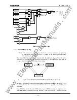
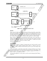
Timing synchronization
When the GPS signal is received normally at every line terminal, the GRL100 performs
synchronized sampling based on the received clock signal. The GRL100 can provide a backup
synchronization system if the GPS signal is interrupted at one or more terminals, and perform
synchronized sampling without any external reference clock. The backup system becomes valid
by setting the scheme switch [GPSBAK] to "ON".
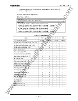
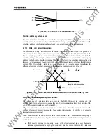
In the backup modes, the percentage restraint in the small current region can be increased from
the normal 16.7% ((1/6)Ir in Figure 2.16.1.1) in accordance with the PDTD setting which is the
probable transmission delay time difference between send and receive channels.
Backup modes, Mode 1, 2A and 2B are initialised when the backup system is set valid.
If the GPS signal interruption occurs when the backup is set invalid, the sampling runs based on
the local clock. When the arrival time of the remote signal measured from local sampling instant
deviates from a nominal time, the protection is blocked.
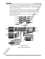
Mode 0:
When the GPS signal is received normally, the sampling is performed synchronizing
with the received clock signal thus realizing synchronized sampling at all terminals. Difference
of the transmission delay time for the channel in each direction and fluctuation of the delay time
can be permitted.
The GRL100 performs the protection based on the nominal current differential characteristics.
When the GPS signal has interrupted for more than ten seconds at any of the terminals, the mode
changes to Mode 1 at all terminals.
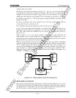
Mode 1:
The terminal which loses its GPS signal first functions as the slave terminal. If all
terminals lose their signals simultaneously, then the scheme switch [SP.SYN] setting determines
which terminal functions as the slave or master. The slave terminal adjusts the local sampling
timing to synchronize the sampling with other terminal which is receiving the GPS signal
regularly or with the master terminal.
Note
: When two terminals are receiving the GPS signal regularly, the slave terminal
synchronizes with the terminal that is interlinked with port 2 of the slave terminal.
When the GPS signal has been restored, the mode shifts from Mode 1 back to Mode 0.
If, during Mode 1 operation, a failure occurs in the communication system, the sampling timing
adjustment is disabled and each terminal runs free. If the free running continues over the time
determined by the PDTD setting or the apparent phase difference exceeds the value determined
by the PDTD setting, the mode shifts from Mode 1 to Mode 2A at all terminals.
Mode 2A
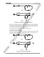
: In this mode, the intra-system synchronization described in 2.2.7.1 is applied
assuming that the transmission delay time for the channel in each direction is identical.
Fluctuation of the delay time can be permitted.
The current differential protection is blocked in this mode.
When the GPS signal has been restored, the mode shifts from Mode 2A to Mode 0.
If the GPS signal interruption occurs a set period following energisation of the relay power
supply or the mode returned to Mode 0 from Mode 1, 2A or 2B, then the transmission delay time
measurement will not be completed in Mode 0, and the mode changes to Mode 2A.
When the apparent current phase difference has stayed within the value determined by the PDTD
setting, the scheme switch [AUTO2B] for automatic mode change is set to "ON" and [TERM] is
set to "2TERM", the mode changes from Mode 2A to Mode 2B at both terminals.
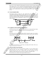
The mode can be changed to Mode 2B manually through a binary input signal "Mode 2B
initiation" or user interface. Before this operation, it must be checked that the transmission delay
www
. ElectricalPartManuals
. com
Summary of Contents for GRL100-701B
Page 329: ... 328 6 F 2 S 0 8 5 0 w w w E l e c t r i c a l P a r t M a n u a l s c o m ...
Page 339: ... 338 6 F 2 S 0 8 5 0 w w w E l e c t r i c a l P a r t M a n u a l s c o m ...
Page 351: ... 350 6 F 2 S 0 8 5 0 w w w E l e c t r i c a l P a r t M a n u a l s c o m ...
Page 381: ... 380 6 F 2 S 0 8 5 0 w w w E l e c t r i c a l P a r t M a n u a l s c o m ...
Page 413: ... 412 6 F 2 S 0 8 5 0 w w w E l e c t r i c a l P a r t M a n u a l s c o m ...
Page 417: ... 416 6 F 2 S 0 8 5 0 w w w E l e c t r i c a l P a r t M a n u a l s c o m ...
Page 453: ... 452 6 F 2 S 0 8 5 0 w w w E l e c t r i c a l P a r t M a n u a l s c o m ...
Page 457: ... 456 6 F 2 S 0 8 5 0 w w w E l e c t r i c a l P a r t M a n u a l s c o m ...
Page 473: ...w w w E l e c t r i c a l P a r t M a n u a l s c o m ...


