253
6
F
2
S
0
8
5
0
6.5.1.3 Distance Measuring Element Z1, Z2, Z3, Z4, ZR and PSB
Phase fault element reach test
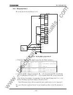
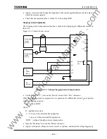
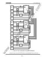
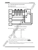
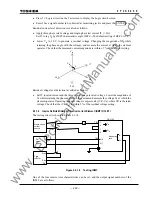
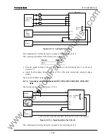
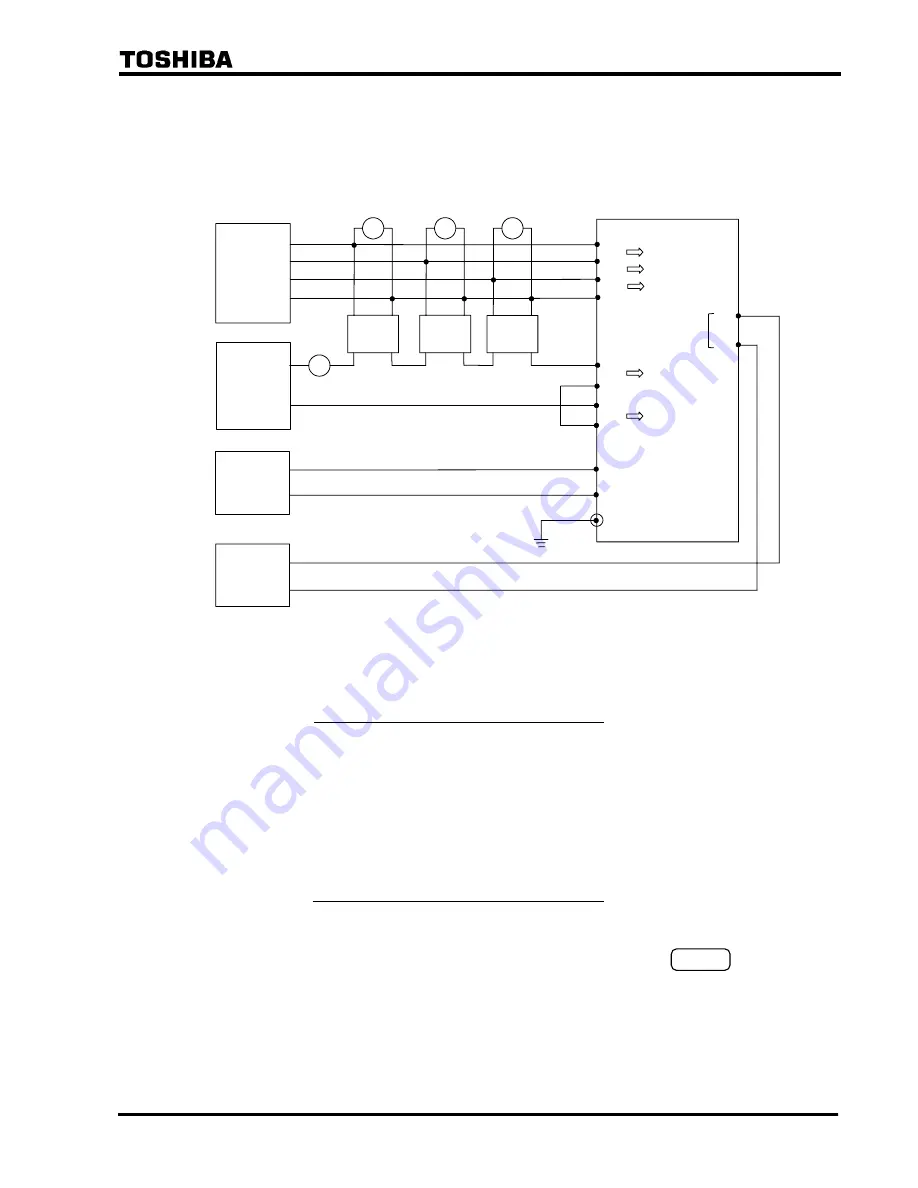
The test voltage and current input test circuit is shown in Figure 6.5.1.6.
Three-phase
voltage
source
A
φ
V
TB1
-12
-11
Va
V
V
φ
φ
Single-phase
current
source
DC
voltmeter
-13
-14
TB1
-2
-1
-3
-4
-A16
-A17
E
TB4
Vc
Vb
Ia
Ib
GRL100
DC
power
supply
+
−
Monitoring
jack
A
0V
Figure 6.5.1.6 Testing Phase-Fault Element
Phase fault elements and their output signal numbers are listed below.
Measuring element
Signal number
Z1S-AB 575
Z2S-AB 578
Z3S-AB 581
Z4S-AB 584
ZRS-AB 364
PSBSIN-AB 596
PSBSOUT-AB 593
•
Press 5 (=Logic circuit) on the "Test" screen to display the "Logic circuit" screen.
•
Enter a signal number to be observed at monitoring jack A and press the ENTER key.
•
Apply three-phase rated voltage.
•
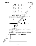
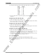
Choose a test current IT by referring to the table below, the table shows the relationship
between the reach setting, test current and measuring error.
www
. ElectricalPartManuals
. com
Summary of Contents for GRL100-701B
Page 329: ... 328 6 F 2 S 0 8 5 0 w w w E l e c t r i c a l P a r t M a n u a l s c o m ...
Page 339: ... 338 6 F 2 S 0 8 5 0 w w w E l e c t r i c a l P a r t M a n u a l s c o m ...
Page 351: ... 350 6 F 2 S 0 8 5 0 w w w E l e c t r i c a l P a r t M a n u a l s c o m ...
Page 381: ... 380 6 F 2 S 0 8 5 0 w w w E l e c t r i c a l P a r t M a n u a l s c o m ...
Page 413: ... 412 6 F 2 S 0 8 5 0 w w w E l e c t r i c a l P a r t M a n u a l s c o m ...
Page 417: ... 416 6 F 2 S 0 8 5 0 w w w E l e c t r i c a l P a r t M a n u a l s c o m ...
Page 453: ... 452 6 F 2 S 0 8 5 0 w w w E l e c t r i c a l P a r t M a n u a l s c o m ...
Page 457: ... 456 6 F 2 S 0 8 5 0 w w w E l e c t r i c a l P a r t M a n u a l s c o m ...
Page 473: ...w w w E l e c t r i c a l P a r t M a n u a l s c o m ...

