25
6
F
2
S
0
8
5
0
I
=
I’
-
Ic
where,
I = compensated current
I’ = actual measured current
Note that since GRL100 calculates both the charging current and compensated line current on a
sample by sample basis, all necessary phase information is inherently taken into account.
2.2.9 Blind Zone Protection
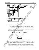
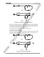
The GRL100 relay has “Out-of-Service Detection Logic” as described in Section 2.2.2. This
logic functions automatically to detect the remote CB or DS (line disconnecting switch) opened
condition as shown in Figure 2.2.9.1. If the remote CB or DS is opened, the received remote
current data is set to “zero” Ampere at the local terminal, and the local relay can be operated with
only local current like a simple over current relay. Therefore, this logic function is used for blind
zone protection.
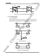
The zone between CB and CT at the remote terminal is the blind zone in Figure 2.2.9.1. If a fault
occurs within this zone, the busbar protection should operate first and trip the CB at the remote
terminal, but the fault remains and the fault current (IF) is fed continuously from the local
terminal. Since this phenomenon is an external fault for the current differential protection
scheme, the blind zone fault cannot be cleared. The fault may be cleared by remote backup
protection following a time delay, but there is a danger of damage being caused to power system
plant. Fast tripping for this type of fault is highly desirable. The Out-of-Service Detection Logic
is effective for a fault where a blind zone between CT and CB on the line exists as shown in
Figure 2.2.9.1.
If the CB and DS condition are introduced at the remote terminal as shown in Figure 2.2.9.1, the
GRL100 relay at the local terminal can operate with only local current and the fault can be
cleared, because the remote current data is automatically cancelled as explained above.
Please note the “CB Close Command” signal must be connected to the GRL100 relay to prevent
unwanted operation for a CB close operation (manual close and/or autoreclose). Unwanted
operation may be caused if the close timing of the CB auxiliary contact is delayed relative to the
CB main contact. Therefore, the CB close command signal resets forcibly the Out-of-Service
Detection Logic before the CB main contact is closed.
CB and DS status signals are input by PLC. If the out-of-service detection is not used, its logic
can be blocked by the scheme switch [OTD].
www
. ElectricalPartManuals
. com
Summary of Contents for GRL100-701B
Page 329: ... 328 6 F 2 S 0 8 5 0 w w w E l e c t r i c a l P a r t M a n u a l s c o m ...
Page 339: ... 338 6 F 2 S 0 8 5 0 w w w E l e c t r i c a l P a r t M a n u a l s c o m ...
Page 351: ... 350 6 F 2 S 0 8 5 0 w w w E l e c t r i c a l P a r t M a n u a l s c o m ...
Page 381: ... 380 6 F 2 S 0 8 5 0 w w w E l e c t r i c a l P a r t M a n u a l s c o m ...
Page 413: ... 412 6 F 2 S 0 8 5 0 w w w E l e c t r i c a l P a r t M a n u a l s c o m ...
Page 417: ... 416 6 F 2 S 0 8 5 0 w w w E l e c t r i c a l P a r t M a n u a l s c o m ...
Page 453: ... 452 6 F 2 S 0 8 5 0 w w w E l e c t r i c a l P a r t M a n u a l s c o m ...
Page 457: ... 456 6 F 2 S 0 8 5 0 w w w E l e c t r i c a l P a r t M a n u a l s c o m ...
Page 473: ...w w w E l e c t r i c a l P a r t M a n u a l s c o m ...

