272
6
F
2
S
0
8
5
0
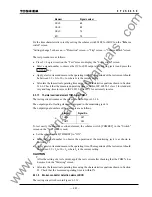
Check that the operating time is 1-1.5 cycle plus zone 3 timer setting.
Check that the indications and recordings are correct.
Zone R tripping
Set the scheme switches [ZRTP] to "On". (The [ZRTP] default setting is "Off".)
Check that three-phase time-delayed final tripping is performed for all kinds of faults. Faults
should be set in the center of zone R.
Check that the operating time is 1-1.5 cycle plus zone R timer setting.
Check that the indications and recordings are correct.
Command Protection
The scheme switch [DISCR] is set "On". The carrier send and receive signals are assigned to the
binary output and input by PLC function.
PUP tripping
Set the scheme switch [CRSCM] to "PUP".
Energize the binary input BIn (assigned to the receive Signal No. 1856 CAR.R1-1) to simulate a
trip permission signal reception and apply a zone 2 fault.
Check that instantaneous single-phase or three-phase tripping is performed depending on the
fault types and setting of autoreclose mode selection switch [ARC-M].
De-energize the binary input BIn and apply a zone 2 fault. Check that PUP tripping does not
occur.
Apply a zone 1 fault, and check that binary output relay BO13 (assigned to the send signal No.
886 CAR-S as default) operates.
Check that the indications and recordings are correct.
POP tripping
Set the scheme switch [CRSCM] to "POP", [WKIT] and [ECHO] to "off".
Energize the binary input BIn to simulate a trip permission signal reception and apply a zone 2
fault.
Check that instantaneous single-phase or three-phase tripping is performed depending on the
fault types and setting of autoreclose mode selection switch [ARC-M].
Set [WKIT] and [ECHO] to "On" and apply a weak-infeed fault. Check that instantaneous
tripping is performed.
De-energize the binary input BIn and apply a zone 2 fault. Check that POP tripping does not
occur.
Apply a zone 2 fault, and check that binary output relay BO13 operates.
Set the scheme switch [ECHO] to "On".
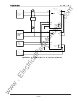
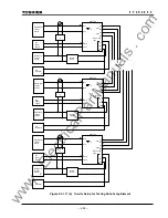
De-energize the binary inputs BI1, BI2 and BI3 to simulate the breaker being open.
Check that binary output relay BO13 operates when the binary input BIn is energized.
Apply a zone 4 fault (reverse fault) while the binary inputs BI1, BI2 and BI3 are energized, and
check that the binary output relay BO13 does not operate when the binary input BIn is energized.
Check that the indications and recordings are correct.
www
. ElectricalPartManuals
. com
Summary of Contents for GRL100-701B
Page 329: ... 328 6 F 2 S 0 8 5 0 w w w E l e c t r i c a l P a r t M a n u a l s c o m ...
Page 339: ... 338 6 F 2 S 0 8 5 0 w w w E l e c t r i c a l P a r t M a n u a l s c o m ...
Page 351: ... 350 6 F 2 S 0 8 5 0 w w w E l e c t r i c a l P a r t M a n u a l s c o m ...
Page 381: ... 380 6 F 2 S 0 8 5 0 w w w E l e c t r i c a l P a r t M a n u a l s c o m ...
Page 413: ... 412 6 F 2 S 0 8 5 0 w w w E l e c t r i c a l P a r t M a n u a l s c o m ...
Page 417: ... 416 6 F 2 S 0 8 5 0 w w w E l e c t r i c a l P a r t M a n u a l s c o m ...
Page 453: ... 452 6 F 2 S 0 8 5 0 w w w E l e c t r i c a l P a r t M a n u a l s c o m ...
Page 457: ... 456 6 F 2 S 0 8 5 0 w w w E l e c t r i c a l P a r t M a n u a l s c o m ...
Page 473: ...w w w E l e c t r i c a l P a r t M a n u a l s c o m ...

