346
6
F
2
S
0
8
5
0
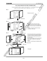
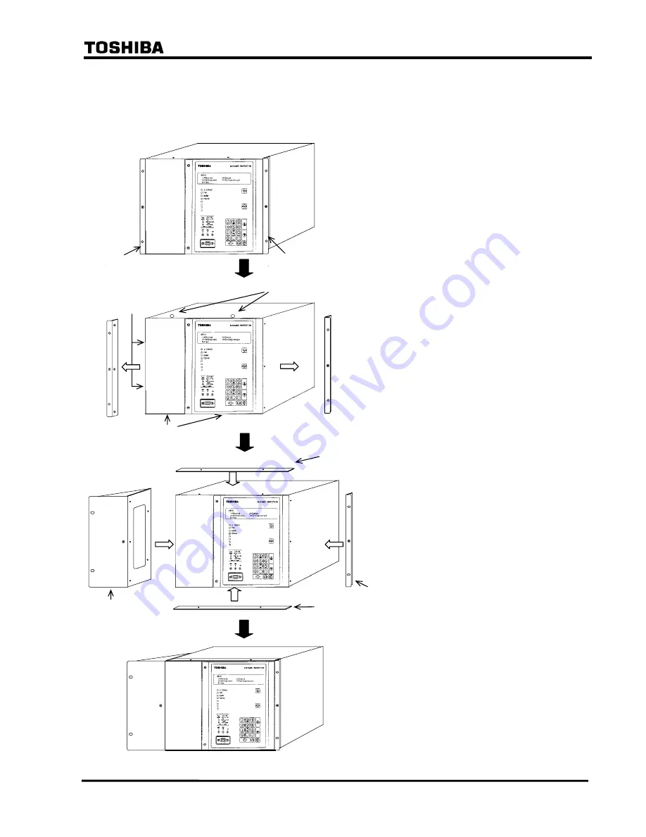
How to Mount Attachment Kit for Rack-Mounting
Caution: Be careful that the relay modules or terminal blocks, etc., are not damage while mounting.
Tighten screws to the specified torque according to the size of screw.
Step 1.
GPS ALARM
SYNC. ALARM
MODE 2A
CF
Step 2.
GPS ALARM
SYNC. ALARM
MODE 2A
CF
Step 3
GPS ALARM
SYNC. ALARM
MODE 2A
CF
Step 4
GPS ALARM
SYNC. ALARM
MODE 2A
CF
Remove case cover.
Remove the left and right brackets by
unscrewing the three screws respectively,
then remove two screws on left side of the
relay.
And then, remove four seals on the top
and bottom of the relay.
Right bracket
Left bracket
Top bar
Bottom bar
Mount the small bracket by screwing three
countersunk head screws(M4x6) and apply
adhesives to the screws to prevent them
from loosening.
Mount the large bracket by five round head
screws(M4x10) with washer and spring
washer.
And then, mount the top and bottom bars by
Small bracket
Large bracket
Completed.
Seal
Seal
Screw
www
. ElectricalPartManuals
. com
Summary of Contents for GRL100-701B
Page 329: ... 328 6 F 2 S 0 8 5 0 w w w E l e c t r i c a l P a r t M a n u a l s c o m ...
Page 339: ... 338 6 F 2 S 0 8 5 0 w w w E l e c t r i c a l P a r t M a n u a l s c o m ...
Page 351: ... 350 6 F 2 S 0 8 5 0 w w w E l e c t r i c a l P a r t M a n u a l s c o m ...
Page 381: ... 380 6 F 2 S 0 8 5 0 w w w E l e c t r i c a l P a r t M a n u a l s c o m ...
Page 413: ... 412 6 F 2 S 0 8 5 0 w w w E l e c t r i c a l P a r t M a n u a l s c o m ...
Page 417: ... 416 6 F 2 S 0 8 5 0 w w w E l e c t r i c a l P a r t M a n u a l s c o m ...
Page 453: ... 452 6 F 2 S 0 8 5 0 w w w E l e c t r i c a l P a r t M a n u a l s c o m ...
Page 457: ... 456 6 F 2 S 0 8 5 0 w w w E l e c t r i c a l P a r t M a n u a l s c o m ...
Page 473: ...w w w E l e c t r i c a l P a r t M a n u a l s c o m ...

