400
6
F
2
S
0
8
5
0
CT REQUIREMENT
Ideally it would be preferable to employ current transformers that did not saturate; this is
particularly desirable if operation of the protection is to be avoided during external faults.
However, there are circumstances due to accommodation requirements and occasionally on the
basis of cost where this is not always possible.
The type GRL100-700 is a current differential with back-up distance protection. CT requirement
for GRL100-700 is determined by the requirement for current differential protection and for
distance protection.
CASE 1. The case with the distance protection applied as a main protection in addition to the
current differential protection
When the distance protection is applied as a main protection the CT requirement for GRL100
must be considered as part of the combined requirements for both protections.
<Step 1> Check the maximum through fault current I
fmaxth
I
fmaxth
< 65 X I
n
where,
I
fmaxth
: Secondary maximum through fault current
I
n
:Rated secondary current
<Step 2> Check the CT satisfies the condition given by table K-1 or K-2 depending on CT types.
Each table has 4 requirements. Every requirement must be satisfied.
<Knee point voltage of CTs is given>
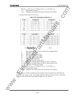
Table K-1 CT Requirement defined by V
k
Td [ms]
Requirement 1
Requirement 2
35
V
k
≧
I
fmax
(R
ct
+ R
2
)
×
3 V
k
≧
I
f_z1_max
(R
ct
+ R
2
)
×
6
50
V
k
≧
I
fmax
(R
ct
+ R
2
)
×
3 V
k
≧
I
f_z1_max
(R
ct
+ R
2
)
×
7
75
V
k
≧
I
fmax
(R
ct
+ R
2
)
×
4 V
k
≧
I
f_z1_max
(R
ct
+ R
2
)
×
8
100
V
k
≧
I
fmax
(R
ct
+ R
2
)
×
4 V
k
≧
I
f_z1_max
(R
ct
+ R
2
)
×
8
150
V
k
≧
I
fmax
(R
ct
+ R
2
)
×
8 V
k
≧
I
f_z1_max
(R
ct
+ R
2
)
×
8
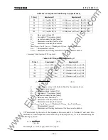
Td [ms]
Requirement 3
Requirement 4
35
V
k
≧
I
f_rev_max
(Rct+ R
2
)
×
2 V
k
≧
I
Lmax
(Rct+ R
2
)
×
14.4
50
V
k
≧
I
f_rev_max
(Rct+ R
2
)
×
3 V
k
≧
I
Lmax
(Rct+ R
2
)
×
20
75
V
k
≧
I
f_rev_max
(Rct+ R
2
)
×
6 V
k
≧
I
Lmax
(Rct+ R
2
)
×
28.8
100
V
k
≧
I
f_rev_max
(Rct+ R
2
)
×
6 V
k
≧
I
Lmax
(Rct+ R
2
)
×
36.8
150
V
k
≧
I
f_rev_max
(Rct+ R
2
)
×
6 V
k
≧
I
Lmax
(Rct+ R
2
)
×
50.4
V
k
: Knee point voltage [V]
R
ct
: Secondary CT resistance [ohms]
R
2
: Actual secondary burden [ohms]
I
fmax
: Maximum secondary fault current
I
f_z1_max
: Maximum secondary fault current at the zone 1 reach point
I
f_rev_max
: Maximum secondary fault current for a close-up reverse fault
I
Lmax
: Maximum
secondary load current
www
. ElectricalPartManuals
. com
Summary of Contents for GRL100-701B
Page 329: ... 328 6 F 2 S 0 8 5 0 w w w E l e c t r i c a l P a r t M a n u a l s c o m ...
Page 339: ... 338 6 F 2 S 0 8 5 0 w w w E l e c t r i c a l P a r t M a n u a l s c o m ...
Page 351: ... 350 6 F 2 S 0 8 5 0 w w w E l e c t r i c a l P a r t M a n u a l s c o m ...
Page 381: ... 380 6 F 2 S 0 8 5 0 w w w E l e c t r i c a l P a r t M a n u a l s c o m ...
Page 413: ... 412 6 F 2 S 0 8 5 0 w w w E l e c t r i c a l P a r t M a n u a l s c o m ...
Page 417: ... 416 6 F 2 S 0 8 5 0 w w w E l e c t r i c a l P a r t M a n u a l s c o m ...
Page 453: ... 452 6 F 2 S 0 8 5 0 w w w E l e c t r i c a l P a r t M a n u a l s c o m ...
Page 457: ... 456 6 F 2 S 0 8 5 0 w w w E l e c t r i c a l P a r t M a n u a l s c o m ...
Page 473: ...w w w E l e c t r i c a l P a r t M a n u a l s c o m ...

