404
6
F
2
S
0
8
5
0
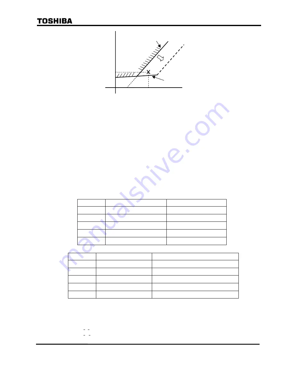
Ir
Id
X+2Y+Z
X+Z
Id = Ir - 2DIFI2
Id = 1/6Ir+5/6DIFI1
2DIFI2
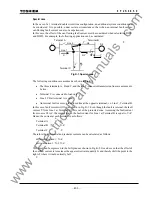
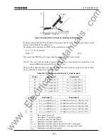
Fig.K-2 Internal fault in Id-Ir plane including out-flow current
In order to ensure
that the
GRL100 relay will
operate correctly in this case, the point shown on the
plot must fall within the operating zone.
According to this requirement, DIFI2 can be calculated as follows.
X +Z > X+2Y+Z
−
2DIFI2
DIFI2 > Y
(K-2)
This means that
DIFI2 must be larger than the amount of out-flowing current.
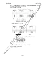
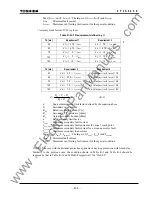
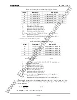
CASE 1. The case with the distance protection applied as a main protection in addition to the
current differential protection for the special case
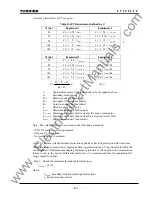
Therefore the condition shown in Table K-1 and Table K-2 should be replaced by that in
Table
K-5 and Table K-6 respectively for “CASE 1”.
Table K-5 CT Requirement defined by V
k
(Special case)
Td [ms]
Requirement 1
Requirement 2
35
V
k
≧
I
fmax
(R
ct
+ R
2
)
×
3 V
k
≧
I
f_z1_max
(R
ct
+ R
2
)
×
6
50
V
k
≧
I
fmax
(R
ct
+ R
2
)
×
3 V
k
≧
I
f_z1_max
(R
ct
+ R
2
)
×
7
75
V
k
≧
I
fmax
(R
ct
+ R
2
)
×
4 V
k
≧
I
f_z1_max
(R
ct
+ R
2
)
×
8
100
V
k
≧
I
fmax
(R
ct
+ R
2
)
×
4 V
k
≧
I
f_z1_max
(R
ct
+ R
2
)
×
8
150
V
k
≧
I
fmax
(R
ct
+ R
2
)
×
8 V
k
≧
I
f_z1_max
(R
ct
+ R
2
)
×
8
Td [ms]
Requirement 3
Requirement 4
35
V
k
≧
I
f_rev_max
(Rct+ R
2
)
×
2 V
k
>
Max{I
Lmax
+ I
fmin
/2, I
fmaxout
}
×
(R
ct
+ R
2
)
×
14.4
50
V
k
≧
I
f_rev_max
(Rct+ R
2
)
×
3 V
k
>
Max{I
Lmax
+ I
fmin
/2, I
fmaxout
}
×
(R
ct
+ R
2
)
×
20
75
V
k
≧
I
f_rev_max
(Rct+ R
2
)
×
6 V
k
>
Max{I
Lmax
+ I
fmin
/2, I
fmaxout
}
×
(R
ct
+ R
2
)
×
28.8
100
V
k
≧
I
f_rev_max
(Rct+ R
2
)
×
6 V
k
>
Max{I
Lmax
+ I
fmin
/2, I
fmaxout
}
×
(R
ct
+ R
2
)
×
36.8
150
V
k
≧
I
f_rev_max
(Rct+ R
2
)
×
6 V
k
>
Max{I
Lmax
+ I
fmin
/2, I
fmaxout
}
×
(R
ct
+ R
2
)
×
50.4
V
k
: Knee point voltage [V]
R
ct
: Secondary CT resistance [ohms]
R
2
: Actual secondary burden [ohms]
I
fmax
: Maximum secondary fault current
I
f_z1_max
: Maximum secondary fault current at the zone 1 reach point
I
f_rev_max
: Maximum secondary fault current for a close-up reverse fault
I
Lmax
: Maximum
secondary load current
www
. ElectricalPartManuals
. com
Summary of Contents for GRL100-701B
Page 329: ... 328 6 F 2 S 0 8 5 0 w w w E l e c t r i c a l P a r t M a n u a l s c o m ...
Page 339: ... 338 6 F 2 S 0 8 5 0 w w w E l e c t r i c a l P a r t M a n u a l s c o m ...
Page 351: ... 350 6 F 2 S 0 8 5 0 w w w E l e c t r i c a l P a r t M a n u a l s c o m ...
Page 381: ... 380 6 F 2 S 0 8 5 0 w w w E l e c t r i c a l P a r t M a n u a l s c o m ...
Page 413: ... 412 6 F 2 S 0 8 5 0 w w w E l e c t r i c a l P a r t M a n u a l s c o m ...
Page 417: ... 416 6 F 2 S 0 8 5 0 w w w E l e c t r i c a l P a r t M a n u a l s c o m ...
Page 453: ... 452 6 F 2 S 0 8 5 0 w w w E l e c t r i c a l P a r t M a n u a l s c o m ...
Page 457: ... 456 6 F 2 S 0 8 5 0 w w w E l e c t r i c a l P a r t M a n u a l s c o m ...
Page 473: ...w w w E l e c t r i c a l P a r t M a n u a l s c o m ...

