43
6
F
2
S
0
8
5
0
2.3 Distance
Protection
2.3.1 Time-Stepped Distance Protection
2.3.1.1 Application
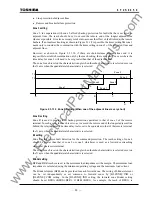
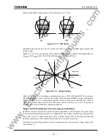
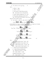
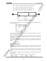
Using reach and tripping time settings coordinated with adjacent lines, the GRL100 provides three
steps of distance protection for forward faults and one backup protection for reverse faults. These
are used as the main protection when telecommunications are not available, or as backup
protection for the protected line and adjacent lines.
The GRL100 has four distance measuring zones for both phase and earth faults, three zones for
forward faults and one zone for reverse faults respectively. The zones can be defined with either
mho-based characteristic or quadrilateral characteristic. The characteristic is selected by setting
the scheme switch [ZS-C] for phase fault and [ZG-C] for earth fault to "Mho" or "Quad".
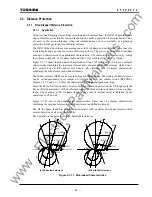
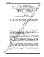
Figure 2.3.1.1 shows the mho-based characteristics. Zone 1 (Z1) and Zone 2 (Z2) have a complex
characteristic combining the reactance element, mho element and blinder element, while Zone 3
(Z3), reverse Zone R (ZR) and reverse Zone 4 (Z4) elements have a complex characteristic
combining the mho element and blinder element.
The blinder element (BFR) can be provided for each forward zone. The setting of blinder element
can be set independently or set common to forward zones by the scheme switch [BLZONE].
Figures 2.3.1.1 and 2.3.1.2 show the characteristics with an independent setting.
Since the Z4 is used for detection of reverse faults in command protection, the Z4 for phase faults
has an offset characteristic with an offset mho element which assures detection of close-up phase
faults. The operation of Z4 for phase faults in the event of internal faults is inhibited by the
operations of Z2 and Z3.
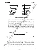
Figure 2.3.1.2 shows the quadrilateral characteristics. These have a complex characteristic
combining the reactance element, directional element and blinder element.
The Z4 for phase faults has an offset characteristic with an offset directional element which
assures detection of close-up phase faults.
The operation is the same as the mho-based characteristics.
Z1S
Z2S
Z3S
Z4S
BFR1S
BRRS
Z1G
Z2G
Z3G
Z4G
BFR1G
BRRG
Z3S
θ
Z1S
θ
1
75
°
Z3G
θ
Z1G
θ
1
75
°
ZRS
ZRG
BRLS
BFR2S
BFRS
BFR2G
BFRG
BRLG
(
a) Phase fault element (b) Earth fault element
Figure 2.3.1.1 Mho-based Characteristics
www
. ElectricalPartManuals
. com
Summary of Contents for GRL100-701B
Page 329: ... 328 6 F 2 S 0 8 5 0 w w w E l e c t r i c a l P a r t M a n u a l s c o m ...
Page 339: ... 338 6 F 2 S 0 8 5 0 w w w E l e c t r i c a l P a r t M a n u a l s c o m ...
Page 351: ... 350 6 F 2 S 0 8 5 0 w w w E l e c t r i c a l P a r t M a n u a l s c o m ...
Page 381: ... 380 6 F 2 S 0 8 5 0 w w w E l e c t r i c a l P a r t M a n u a l s c o m ...
Page 413: ... 412 6 F 2 S 0 8 5 0 w w w E l e c t r i c a l P a r t M a n u a l s c o m ...
Page 417: ... 416 6 F 2 S 0 8 5 0 w w w E l e c t r i c a l P a r t M a n u a l s c o m ...
Page 453: ... 452 6 F 2 S 0 8 5 0 w w w E l e c t r i c a l P a r t M a n u a l s c o m ...
Page 457: ... 456 6 F 2 S 0 8 5 0 w w w E l e c t r i c a l P a r t M a n u a l s c o m ...
Page 473: ...w w w E l e c t r i c a l P a r t M a n u a l s c o m ...

