460
6
F
2
S
0
8
5
0
2. Methods of Replacing the Modules
CAUTION
When handling a module, take anti-static measures such as wearing an earthed
wrist band and placing modules on an earthed conductive mat. Otherwise, many
of the electronic components could suffer damage.
CAUTION
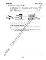
After replacing the SPM module, check all of the settings including the PLC
and IEC103 setting data are restored the original settings.
The initial replacement procedure is as follows:
1). Switch off the DC power supply.
Hazardous voltage may remain in the DC circuit just after switching off the
DC power supply. It takes about 30 seconds for the voltage to discharge.
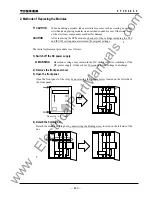
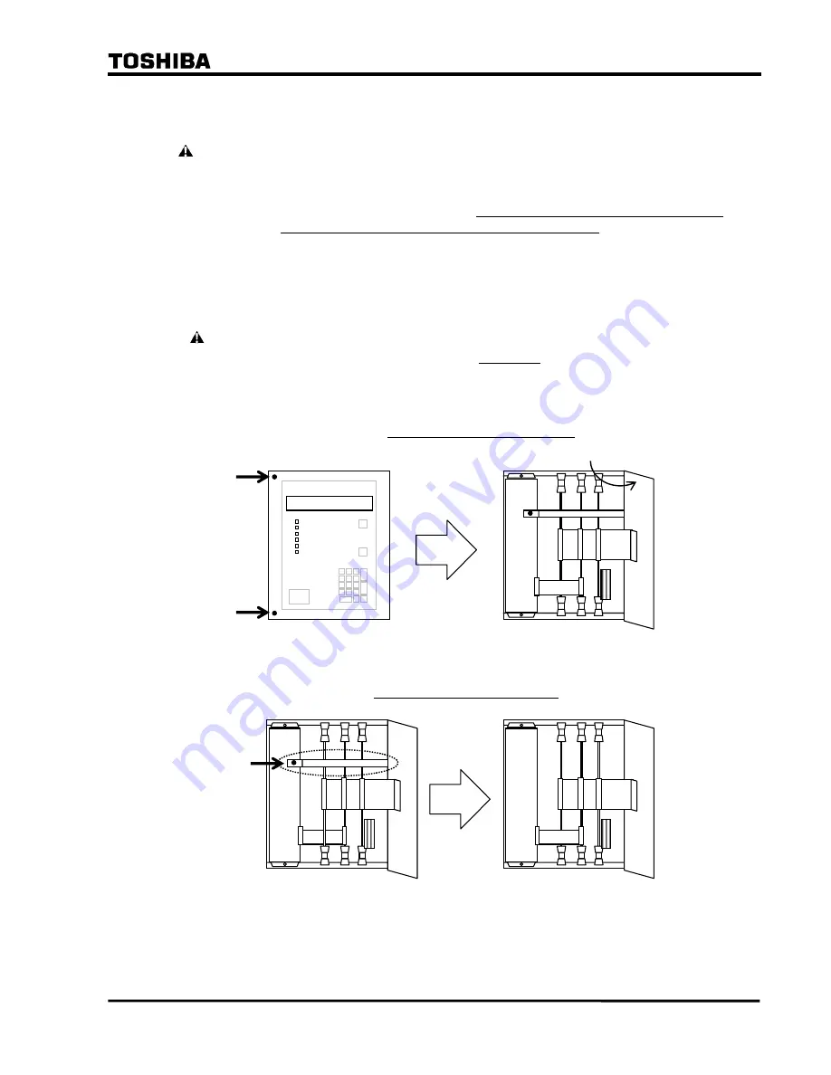
2). Remove the front panel cover.
3). Open the front panel.
Open the front panel of the relay by unscrewing the binding screw located on the left side of
the front panel.
Case size : 1/2”inchs
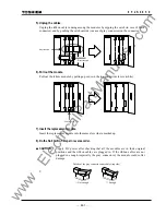
4). Detach the holding bar.
Detach the module holding bar by unscrewing the binding screw located on the left side of the
bar.
WARNING
www
. ElectricalPartManuals
. com
Summary of Contents for GRL100-701B
Page 329: ... 328 6 F 2 S 0 8 5 0 w w w E l e c t r i c a l P a r t M a n u a l s c o m ...
Page 339: ... 338 6 F 2 S 0 8 5 0 w w w E l e c t r i c a l P a r t M a n u a l s c o m ...
Page 351: ... 350 6 F 2 S 0 8 5 0 w w w E l e c t r i c a l P a r t M a n u a l s c o m ...
Page 381: ... 380 6 F 2 S 0 8 5 0 w w w E l e c t r i c a l P a r t M a n u a l s c o m ...
Page 413: ... 412 6 F 2 S 0 8 5 0 w w w E l e c t r i c a l P a r t M a n u a l s c o m ...
Page 417: ... 416 6 F 2 S 0 8 5 0 w w w E l e c t r i c a l P a r t M a n u a l s c o m ...
Page 453: ... 452 6 F 2 S 0 8 5 0 w w w E l e c t r i c a l P a r t M a n u a l s c o m ...
Page 457: ... 456 6 F 2 S 0 8 5 0 w w w E l e c t r i c a l P a r t M a n u a l s c o m ...
Page 473: ...w w w E l e c t r i c a l P a r t M a n u a l s c o m ...

