461
6
F
2
S
0
8
5
0
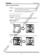
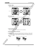
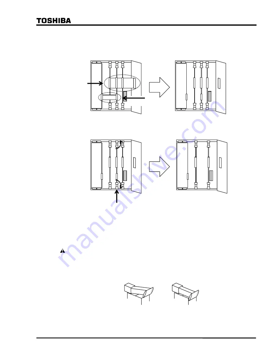
5). Unplug the cables.
Unplug the ribbon cable running among the modules by nipping the catch (in case of black
connector) and by pushing the catch outside (in case of gray connector) on the connector.
6). Pull out the module.
Pull out the failure module by pulling up or down the top and bottom levers (white).
7). Insert the replacement module.
Insert the replacement module into the same slots where marked up.
.
8). Do the No.5 to No.1 steps in reverse order.
CAUTION
Supply DC power after checking that all the modules are in their original
positions and the ribbon cables are plugged in. If the ribbon cables are not
plugged in enough (especially the gray connectors), the module could suffer
damage.
Gray connector
Black connector
SPM module
Details of the gray connector on modules (top side)
×
Not enough
○
Enough
www
. ElectricalPartManuals
. com
Summary of Contents for GRL100-701B
Page 329: ... 328 6 F 2 S 0 8 5 0 w w w E l e c t r i c a l P a r t M a n u a l s c o m ...
Page 339: ... 338 6 F 2 S 0 8 5 0 w w w E l e c t r i c a l P a r t M a n u a l s c o m ...
Page 351: ... 350 6 F 2 S 0 8 5 0 w w w E l e c t r i c a l P a r t M a n u a l s c o m ...
Page 381: ... 380 6 F 2 S 0 8 5 0 w w w E l e c t r i c a l P a r t M a n u a l s c o m ...
Page 413: ... 412 6 F 2 S 0 8 5 0 w w w E l e c t r i c a l P a r t M a n u a l s c o m ...
Page 417: ... 416 6 F 2 S 0 8 5 0 w w w E l e c t r i c a l P a r t M a n u a l s c o m ...
Page 453: ... 452 6 F 2 S 0 8 5 0 w w w E l e c t r i c a l P a r t M a n u a l s c o m ...
Page 457: ... 456 6 F 2 S 0 8 5 0 w w w E l e c t r i c a l P a r t M a n u a l s c o m ...
Page 473: ...w w w E l e c t r i c a l P a r t M a n u a l s c o m ...


